
![]()
![]()
![]()
![]()
![]()
![]()
![]()
![]()
Engineering Creativity for Neuroscience
Museum of Equipments
The currently manufactured constructions of Supertech Instruments can be seen on the Products page. But there were many more equipments developed and manufactured during the long history (since the establishment in 1991) of Supertech Instruments. Most of them are out of date and they have been simply removed from this website as their newer versions have been introduced. But there were a few really interesting, delicate or special equipments developed by Supertech Instruments, which are already not manufactured. The list below is a short memorial of the discontinued, but most valuable development projects and products of our Factory.
There is another purpose, why we publish the most interesting former constructions of Supertech Instruments. Our efforts are mainly focused on design and development activity. We manufacture many products, but we are always working on new development tasks. This collection shows those topics, in which we have notable former experience and knowledge. Upon request any of them or parts of them can be restarted, renewed, modified or further developed in the future. Design of Special Equipments page gives you some more information about the possibility of common development of measuring equipments for your unique purpose.

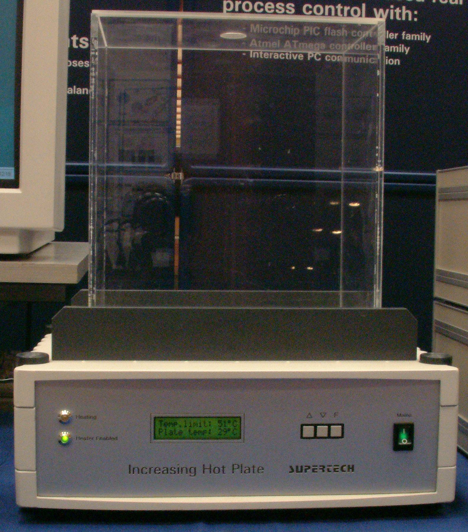
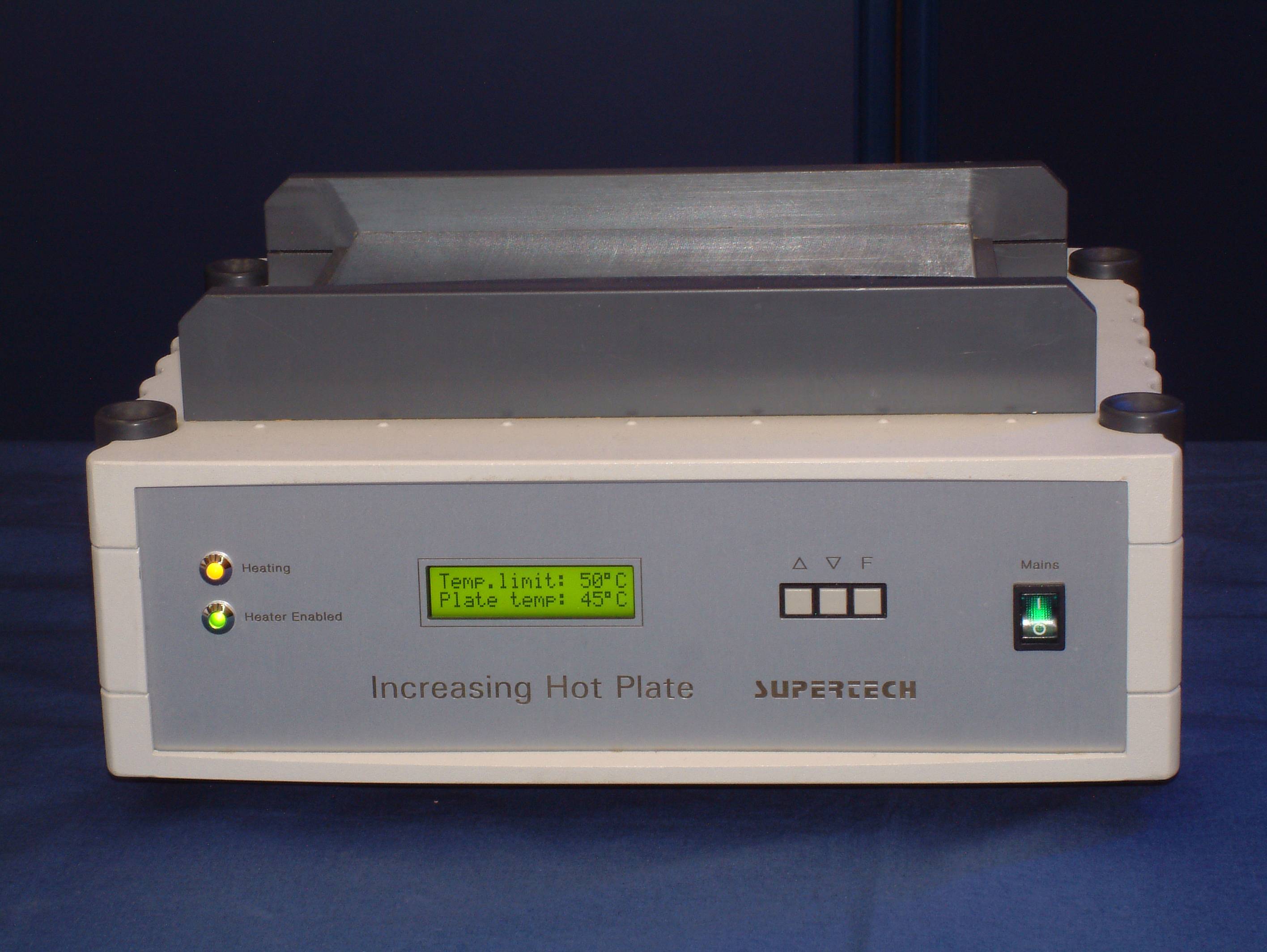
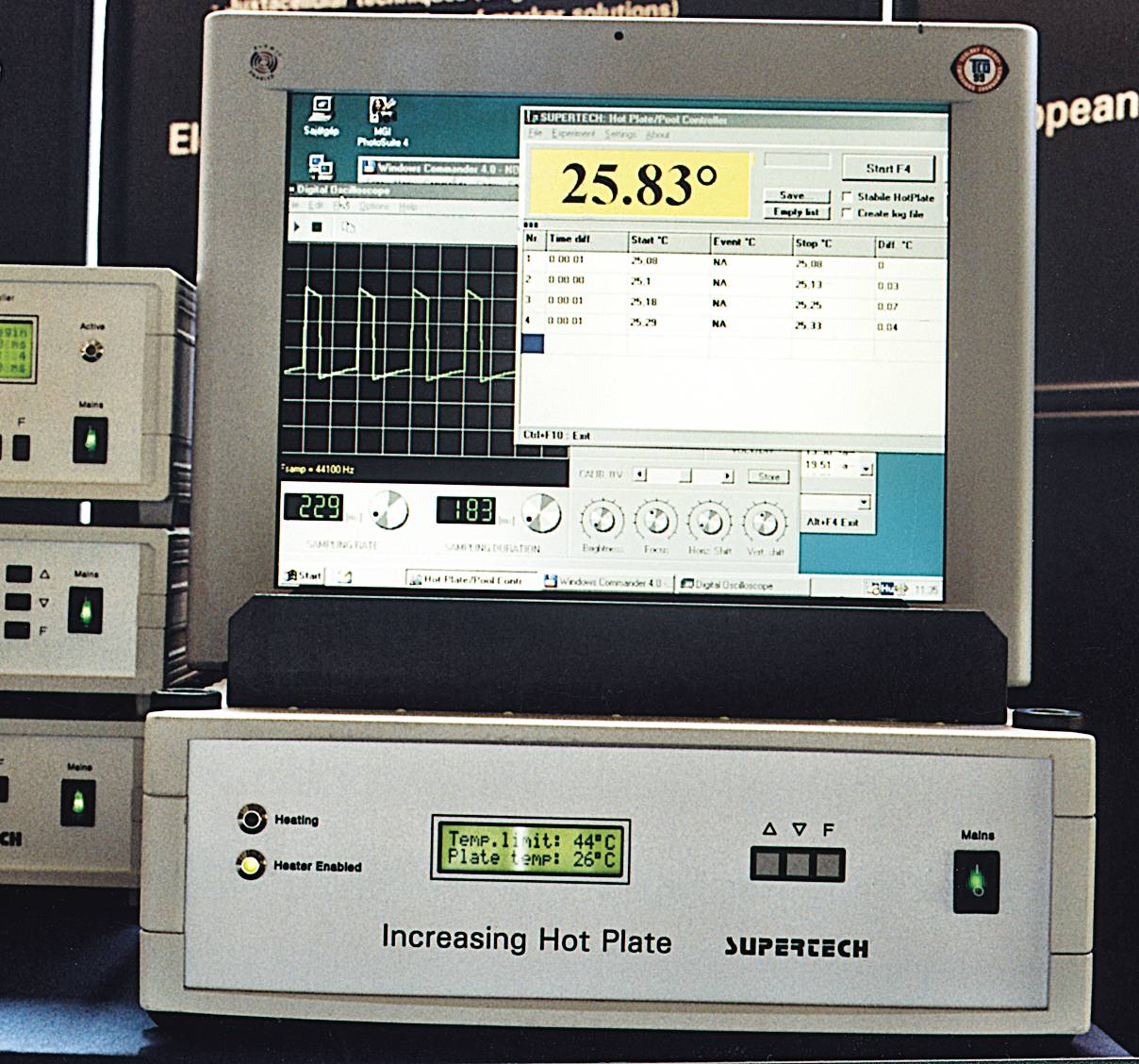
Increasing Temperature Hot Plate
It was developed in 1997. In that time only one similar equipment was available worldwide.
Our Increasing Temperature Hot Plate test equipment was designed for determining the pain threshold in rats or mice. The temperature is slowly increasing with variable heating rates from non-noxious levels until a response is observed or a cut-off temperature is reached. The response is the licking of the hind paw, and the corresponding plate temperature represents the recorded nociceptive end-point. The advantage of Increasing Temperature Hot Plate test over the standard constant-temperature hot-plate test is the higher sensitivity (better in studying the analgesic effects of mild analgesics), and the lack of influences of pre-exposure to the hot-plate before testing.
The equipment was controlled by an IBM-compatible industrial standard PC through its standard Centronics (parallel) port. All the parameters were controlled by the program running on the computer. Moreover the cut-off temperature for safety's sake was controlled by the built-in microcontroller located in the Increasing Temperature Hot Plate equipment, too. A plexiglas box was placed on the top of the plate for possible clear observation of the animal.
 Click on the picture to get it in full size
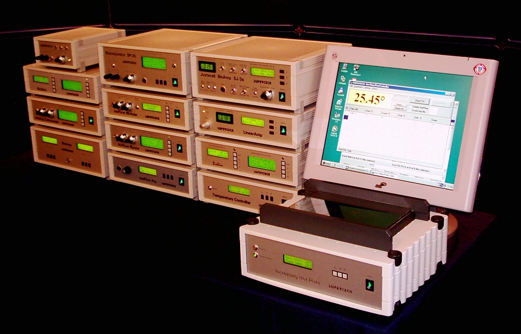 At an exhibition, with many other equipments
Technical data:
Heating elements: a delicate heater surface structure was developed especially to use in this equipment
Maximal temperature difference between the centre and the edge of the plate: 0.5 Centigrade
Heating rates: can be set from 1 Centigrade/min to 6 Centigrade/min, controlled by the PC software. The equipment can be used with higher heating rates (up to 12 Centigrade/min), but the temperature difference on the plate will be increased over the specified value in such cases
Cooling: contact heat dissipation
The size of the heated working surface on the top of the equipment: 200 mm x 150 mm
The height and the volume of the plexiglas box: 250 mm, 3 liters
Computer program: required an IBM-compatible PC running under MS Windows 98 (or higher) operating system
Starting temperature of the measurements: room temperature
Cut-off temperature (hardware, and firmware controlled): can be set from 30 Centigrade to 54 Centigrade
Cut-off temperature (controlled by the PC software): can be set from 30 Centigrade to 54 Centigrade
Dimensions without the plexiglas box: 330 x 260 x 130 mm
References:
Hunskaar, S., Berge, O.G., Hole, K.: A modified hot-plate test sensitive to mild analgesics. Behav. Brain Res. 2: 101-108, 1986.
Tjolsen, A., Rosland, J.H., Berge, O.G., Hole, K.: The increasing-temperature hot-plate test: an improved test of nociception in mice and rats. J. Pharmacol. Methods 3: 241-250, 1991.
Almasi, R., Petho, G., Bolcskei, K., Szolcsanyi, J.: Effect of resiniferatoxin on the noxious heat threshold temperature in the rat: a novel heat allodynia model sensitive to analgesics. British Journal of Pharmacology, 139(1): 49-58, 2003.
Transcranial Electrical Stimulator
Transcranial Electrical Stimulator was developed for human transcranial direct current stimulation (tDCS). The electrical charge and current densities applied by the equipment were far below the threshold for releasing a stimulus and had a modular effect on existing neuronal elements. Depending on the duration, output current, current density and frequency, the stimulation was effective on inhibiting or activating the cortical activity.
Technical Data
Output current ranges:
0 - 100 nA
0 - 1 uA
0 - 10 uA
0 - 100 uA
Compliance voltage: 500 V
Fully isolated, floating power supply for the output circuitry
There was a microcontroller-based timer and sequence controller with 2x16 character LCD on the front plate. This controller provided precise timing of the output current.
The programmable active output period was in the range of 10 - 600 sec, with 10 sec of resolution
There was a nonvolatile memory in the controller to store the setup parameters
Digital real-time current and voltage monitors were located on the front plate
Juxtacell BioAmp
This equipment was a further development of our universal biological BioAmp amplifier. This equipment was optimized for juxtacellular recording (extracellular single cell recording with simultaneous electrophoretic application of tracer solution onto the examined cell).
![]() Click on the picture to get it in full size
Click on the picture to get it in full size
Analog Commander
Analog Commander was a special, single-processor version of the BioStim Pulse Pattern Generator. It was designed to work as an analog command generator for Axopatch patch-clamp amplifiers manufactured by Axon Instruments. Analog Commander had got microprocessor-based bipolar pulse pattern generator and calibrated analog voltage output controls (helical potentiometers).
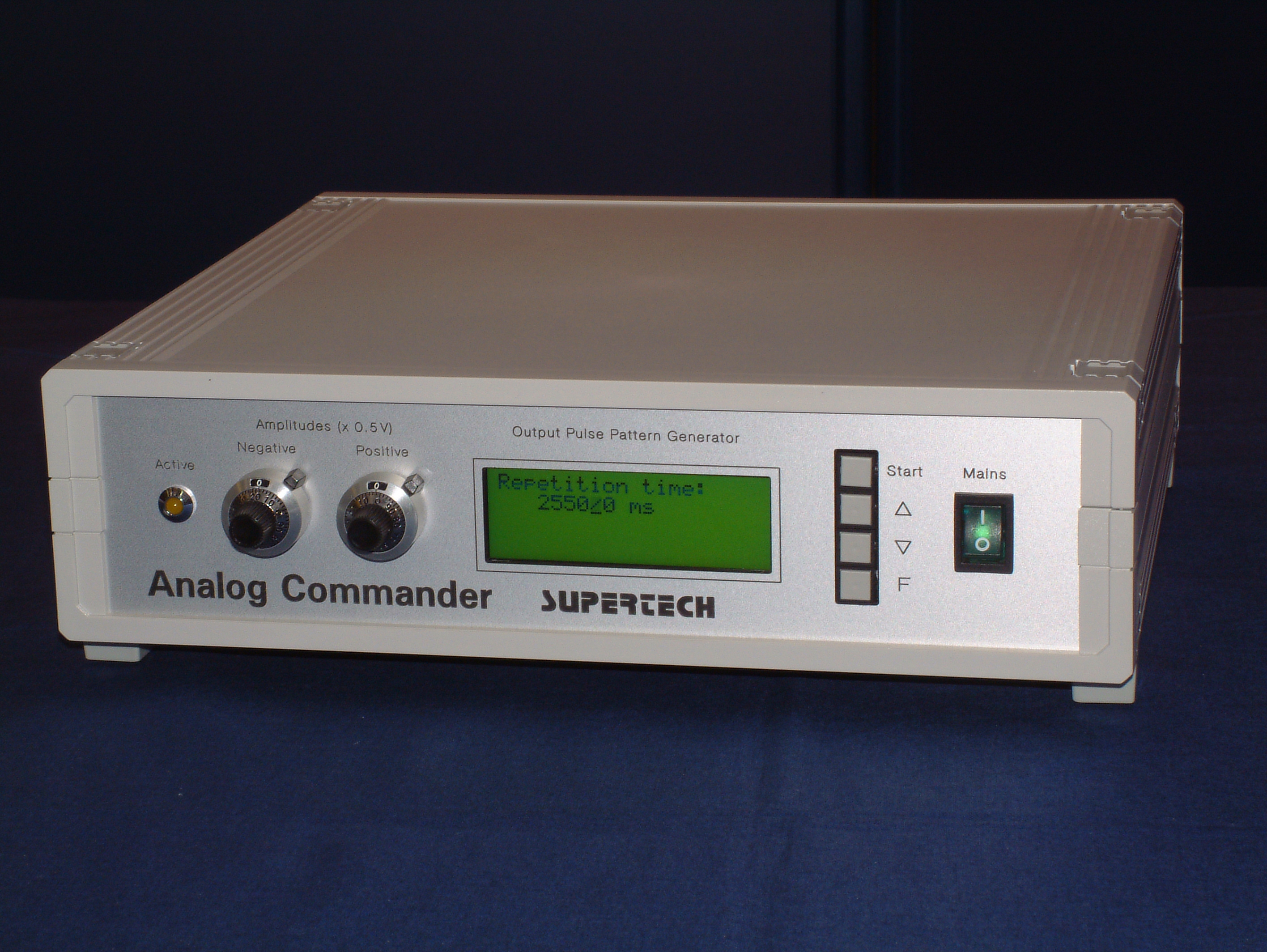 Click on the picture to get it in full size
Laser Heat Exchangers
This was a special product line of Supertech Instruments. The Laser Heat Exchangers were microprocessor-controlled cooling regulators for huge-power industrial lasers. They provided a volume-controlled, cold water flow to cool the lasers.
We have developed different Laser Heat Exchangers up to 50 kW. In the pictures you can see an example.

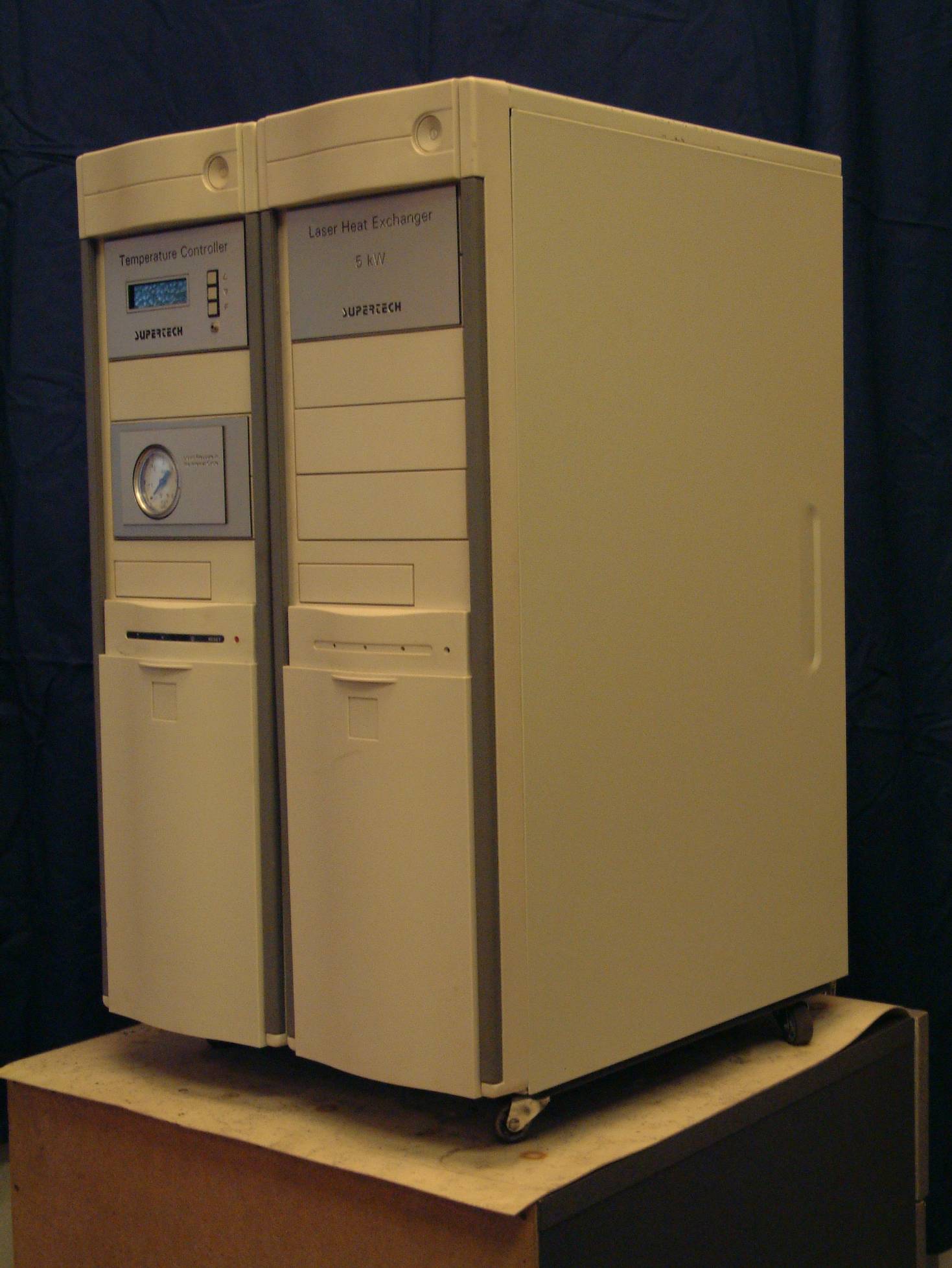
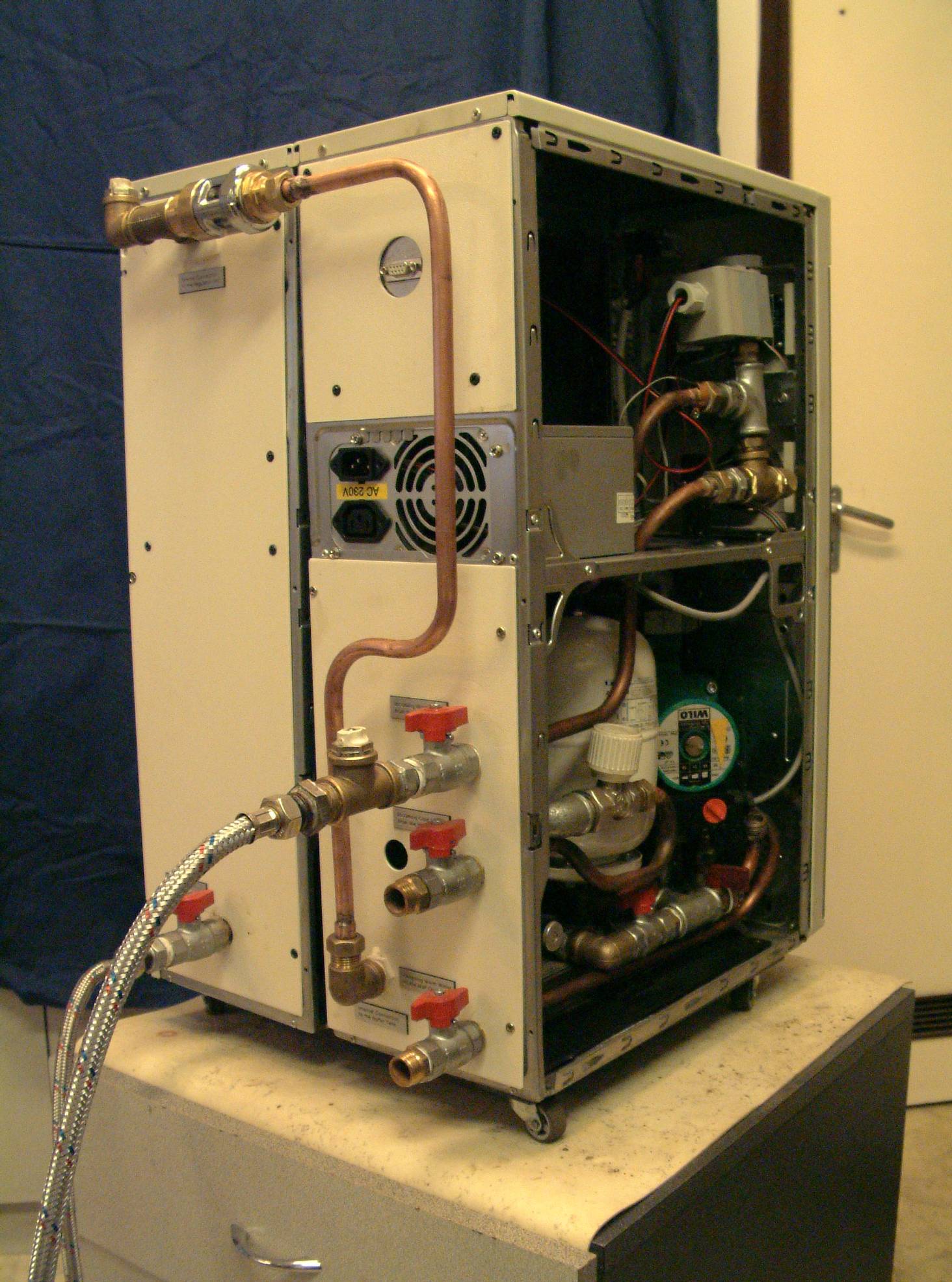 Click on the picture to get it in full size
Lick Detector (Spout) for Monkey
This dual-channel spout equipment was used to provide two different (e.g. sweet and disgusting) solution flows for a monkey to drink. The two spouts and their connection tubes were independent from each other. The geometry of the mouthpiece was optimized for monkeys. There was an optical detector in front of the spouts. The optical axle of the infrared beam was located below the spouts with 5 mm. The electronic box (not shown in the pictures) generates a standard TTL level of output pulse for every touches of the tongue.
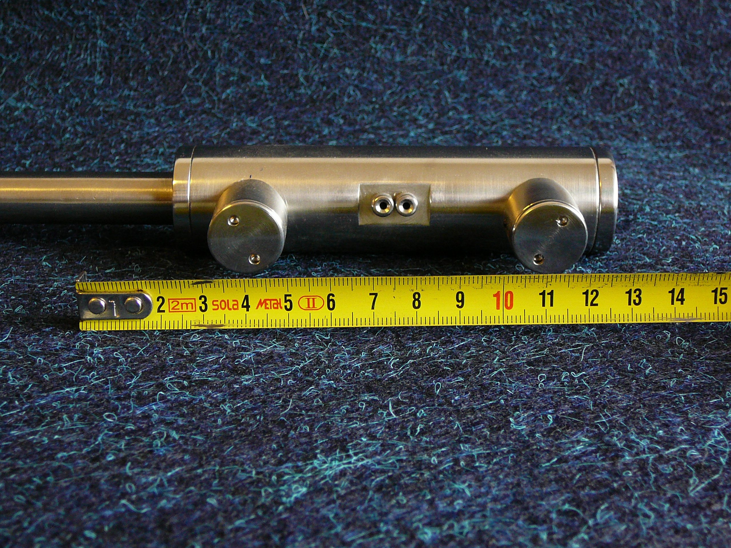
 Click on the picture to get it in full size
Low-cost, General Purpose, 16-channel Data Acquisition Program
Supertech Scope was a simplified, low-cost, general purpose, 16-channel data acquisition program. The full bandwidth of the program was 100 kS/s, but it was limited by the A/D converter card itself, not by the software. The effective bandwidth for one channel could be calculated by division of the full bandwidth with the number of the A/D converter channels used actually. The Supertech Scope program could be used on PCI-1711 (PCI bus version), or PCL-812 (ISA bus version) data acquisition cards manufactured by Advantech.
Combined Heater for Brain Slice Chamber
This heating equipment controlled the temperature of the brain slice chamber and the incoming solution flow together. Later there were new equipments introduced into our product choice instead of this Combined Heater. These newer and current alternates are the In-line Solution Heaters.

 Click on the picture to get it in full size
As you can see in the pictures, the plastic tube could be changed by the user in case of any dirt of infection.
With a stainless steel chamber the heat contact to the brain slice was perfect. We found that plexiglas, teflon or other plastic chambers could not be heated and controlled perfectly.
In this Combined Heater there was an internal temperature sensor, as well.
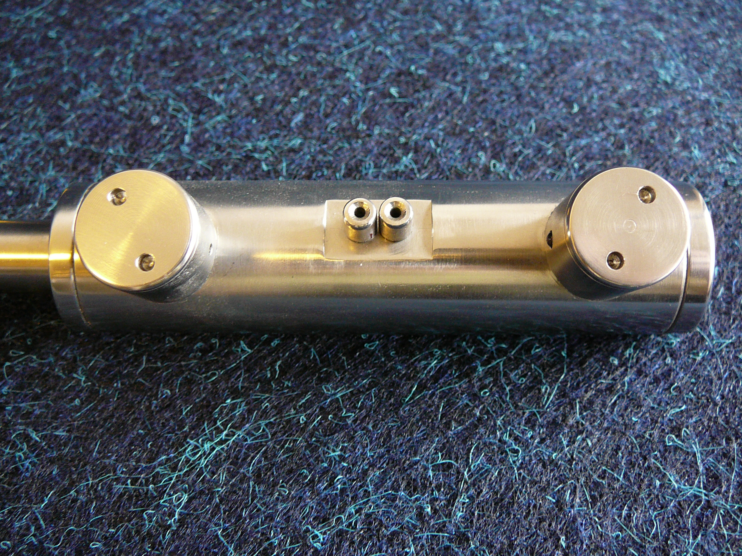
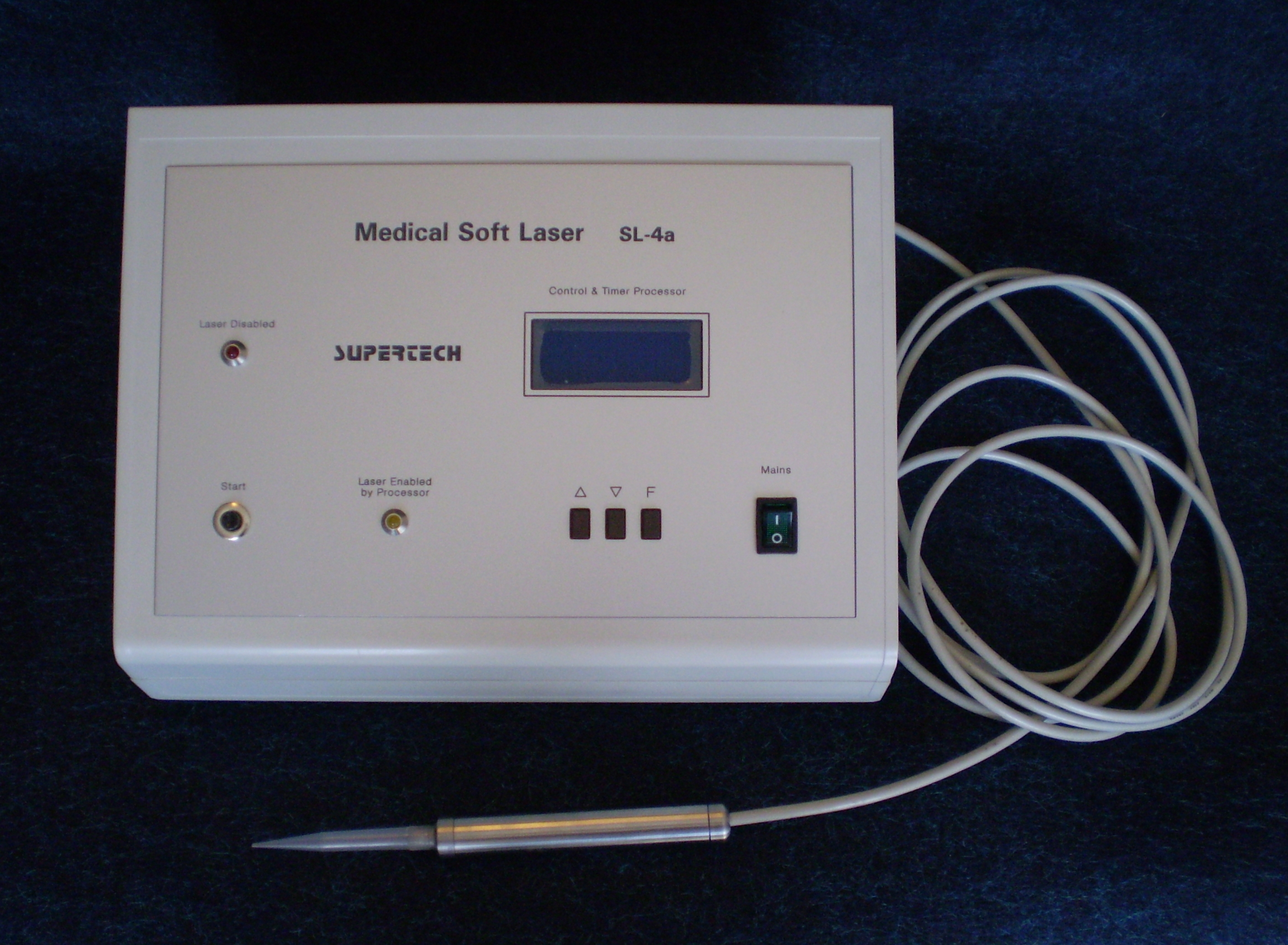
Medical Soft Laser
This equipment has been developed for human applications in dentistry, dermatology, pediatrics, urology and gynecology. Its internal construction and its power supply complied with the EN 60601-1-2:2002 human medical patient safety standard.
Medical Soft Laser SL-4a was a universal soft laser equipment. It could drive any kind of laser diode with any wavelength, up to 1W of optical power (1W is the upper power limit of the soft lasers). This feature provided the opportunity to connect any kind of special headpiece to the equipment. The built-in software provided various lighting patterns for the different application fields.
By default we enclosed a headpiece of 13 mW power and 635 nm wavelength.
 Click on the picture to get it in full size
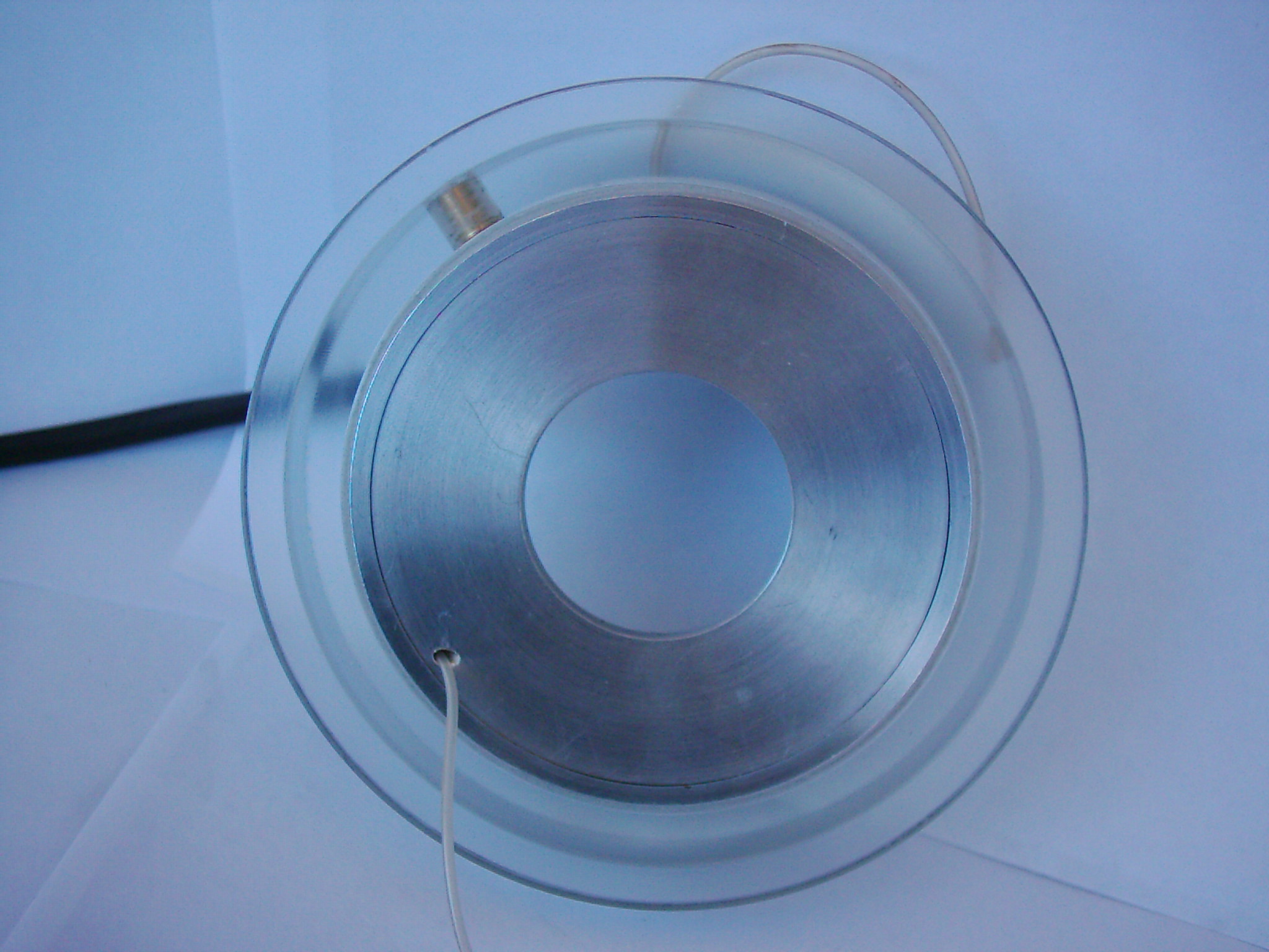
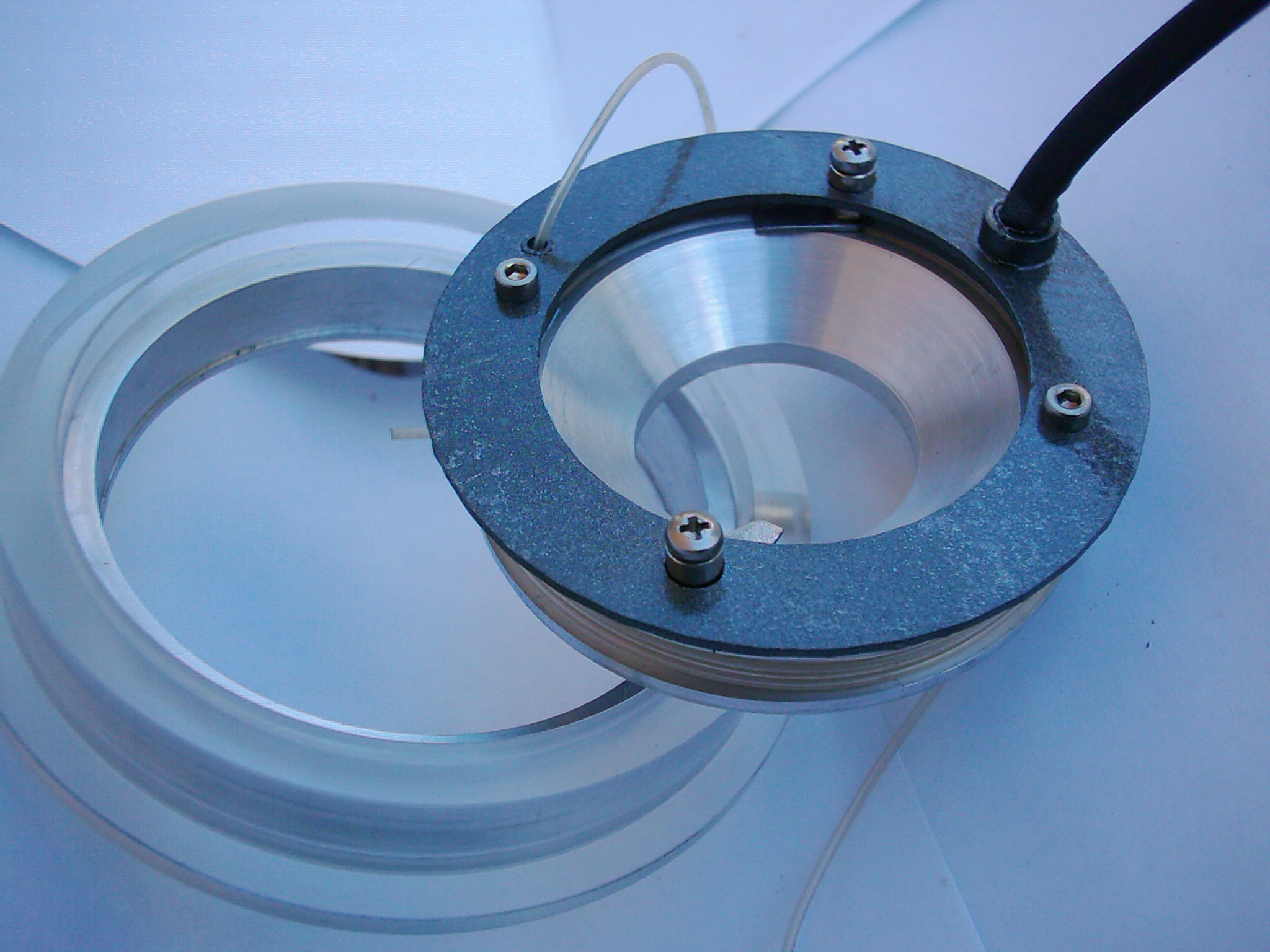
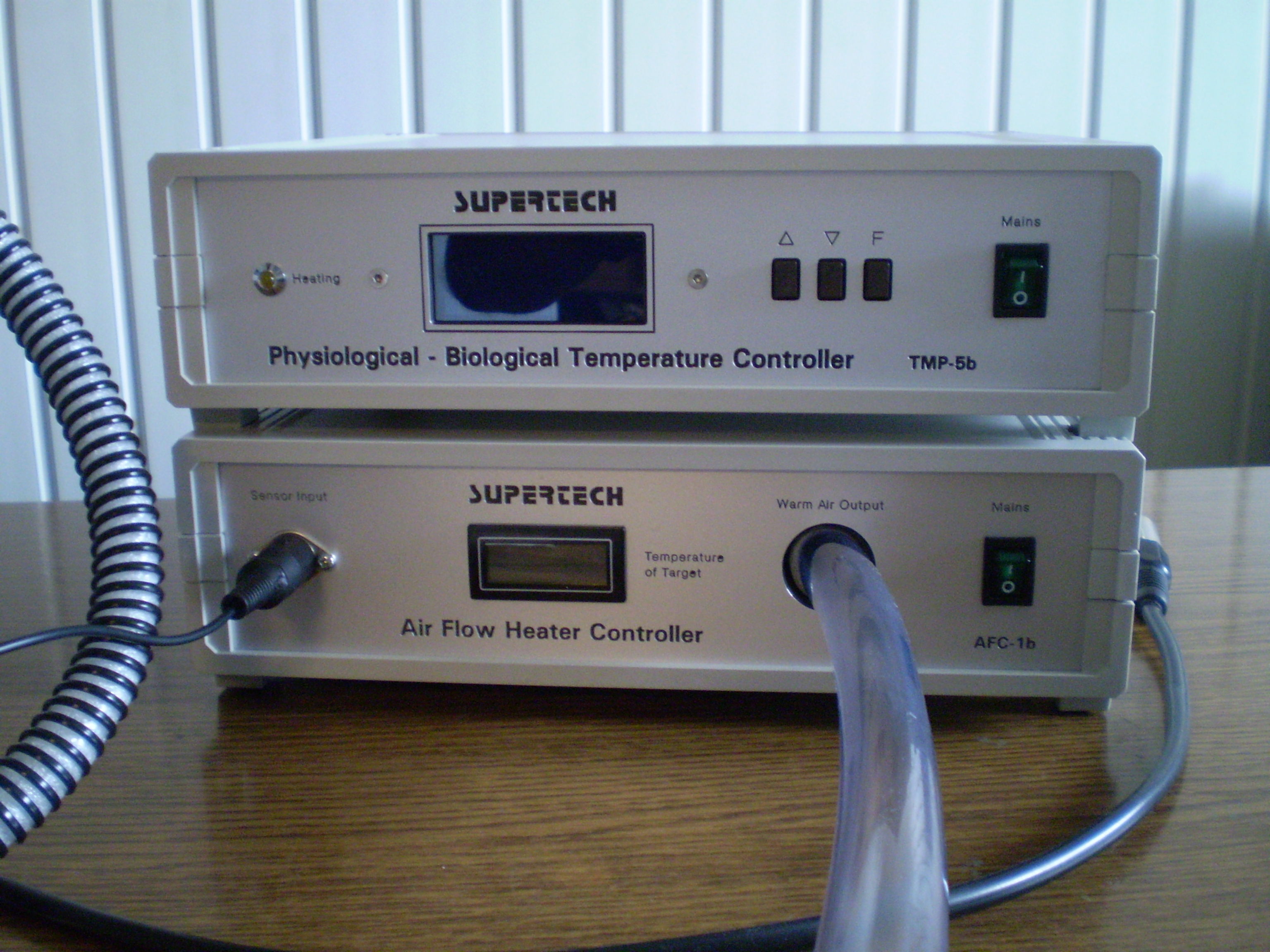
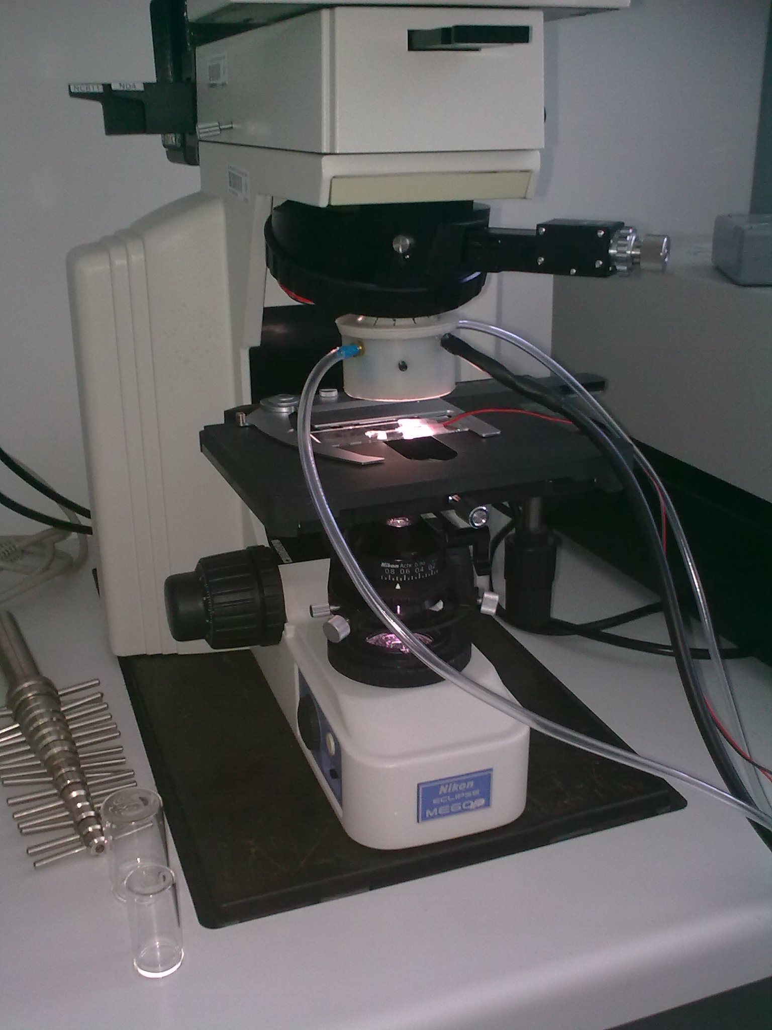
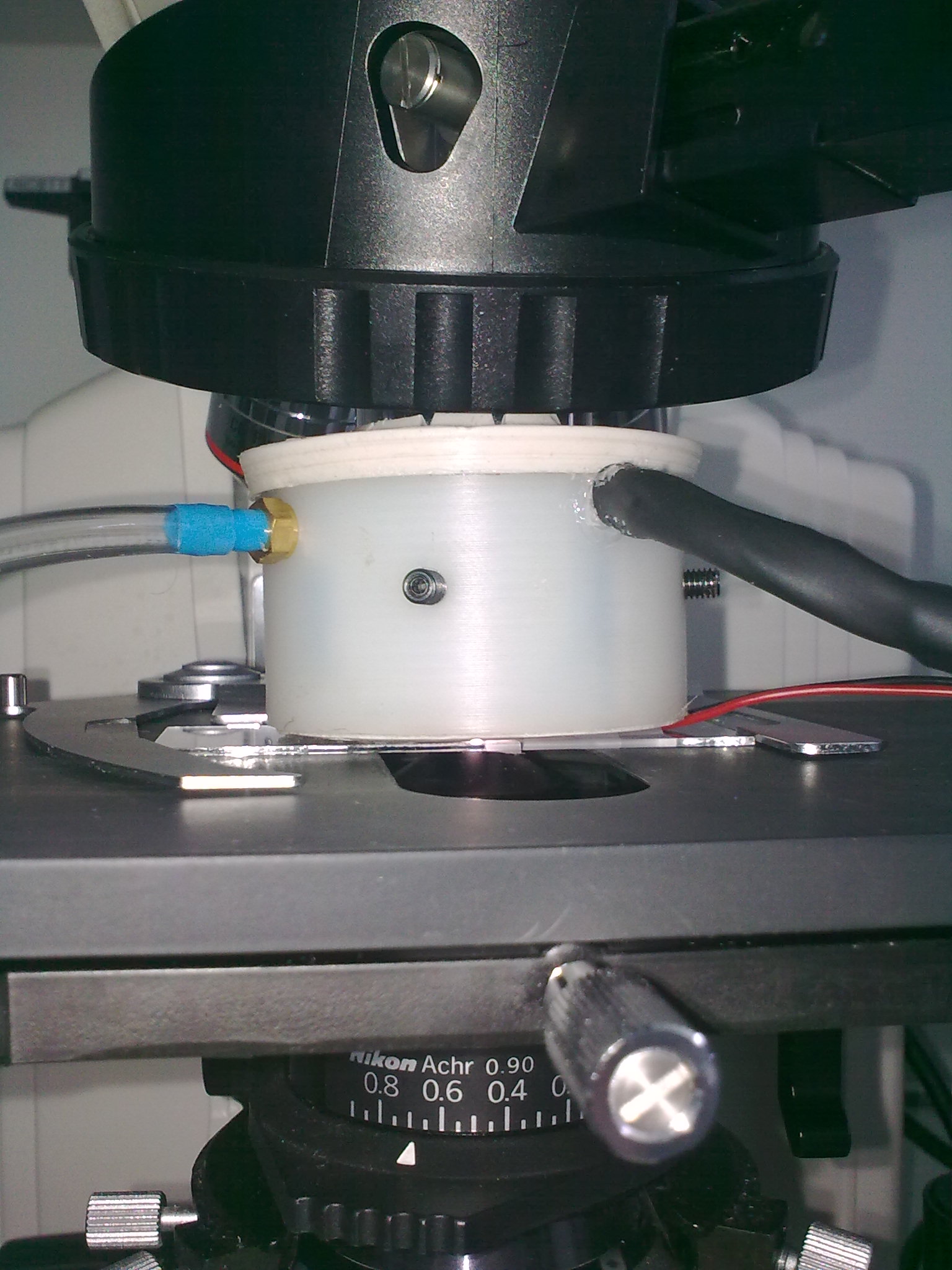
Warm Air Jet Heater System for Incubator, Objective or Sample
The base of this unique heating method was producing high volume of heated air inside the incubator or around the objective or the sample. The flow rate of the air mass and the temperature of the outgoing air flow was accurately controlled. The controller equipments were universal and there were task-specific mechanical and/or thermal interfaces and nosepieces for every heated object.
 Click on the picture to get it in full size
In the pictures you can see the precise heating of an objective without touching the objective mechanically. This was the main goal of the Warm Air Jet Heater method, to protect the expensive and sensitive objective. These pictures show a prototype of the nosepiece.
Warm Air Jet Heater System for Objective system was a set of the following equipments:
• Jet Air Flow Heater Controller with built-in temperature meter
• Physiological - Biological Temperature Controller TMP-5b
• Nosepiece for the objective, with built-in digital DS1820 temperature sensor
MultiAmp V.5 Multichannel Biological Amplifier System
In the past there were three different amplifier systems (BioAmp, MultiAmp and LinearAmp) in our product choice, because the three product lines were optimized for different application fields. BioAmp DC is an up-to-date, highlighted product group of Supertech Instruments for many years, even until now. MultiAmp and LinearAmp families have been retired. This paragraph describes the MultiAmp amplifier family.
MultiAmp was a modular, expandable, multichannel biological amplifier system. We manufactured it for 15 years. It was a great success. It survived five versions under continuous development.
MultiAmp amplifier family was especially powerful in multichannel applications, since such a level of reliability and flexibility was unthinkable in other analogue amplifiers. The top of all that, our MultiAmp amplifier system offered a very reasonable price level in comparison to the number of the amplifier channels. The most important aim during its development was to remove all that features (and the appropriate circuits) which were substituted in the biological data acquisition software packages. This way the dimensions of the circuits could be decreased and the number of channels could be increased efficiently.
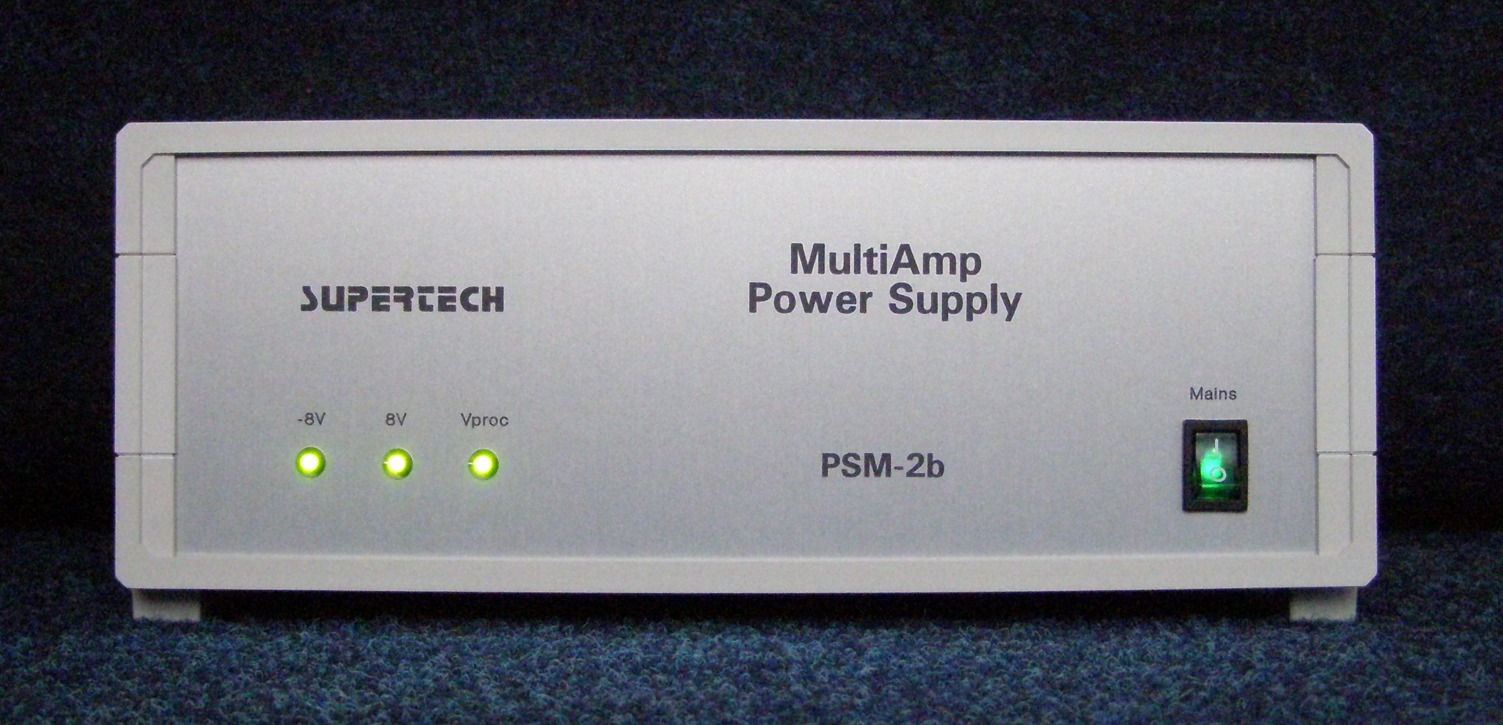
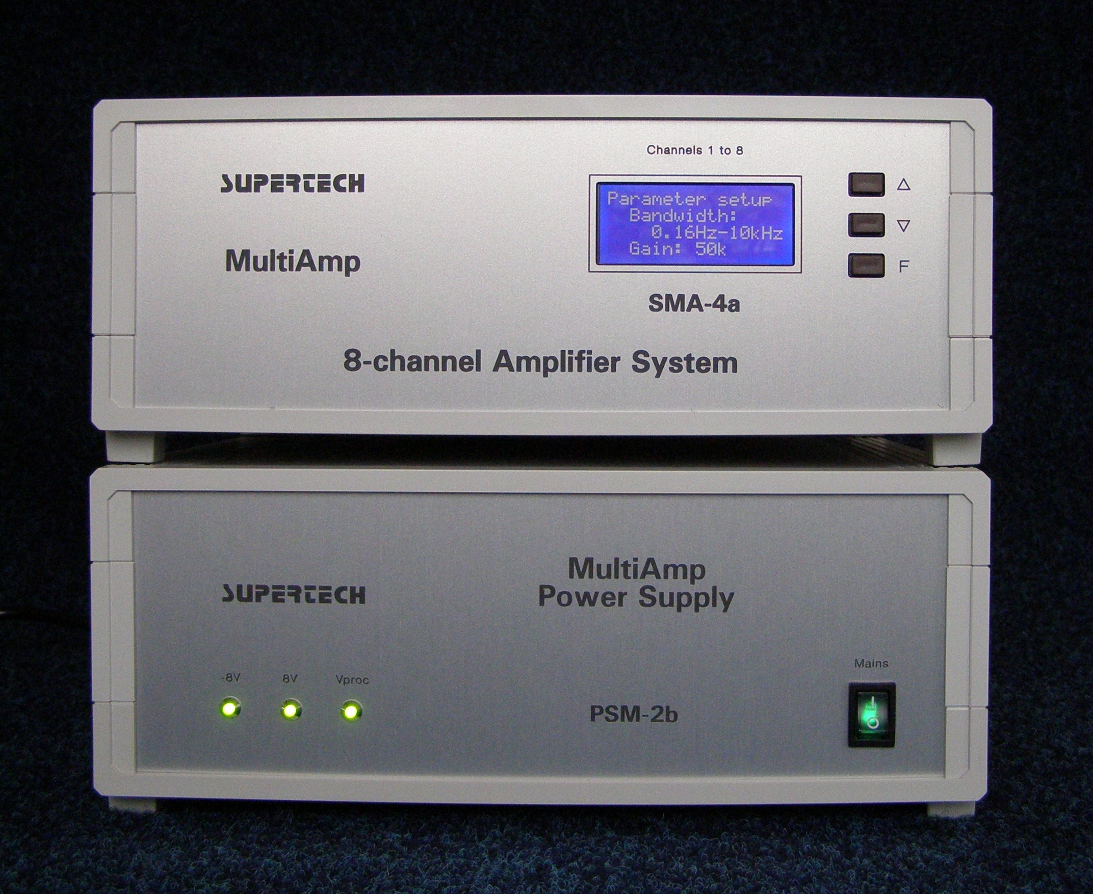 An example: the smallest (8-channel) MultiAmp system
MultiAmp's Main Fields of Applications
• EEG Brain Mapping
• Multichannel recording from brain slices
• Chronic multichannel recording
The Modular Structure of the MultiAmp System
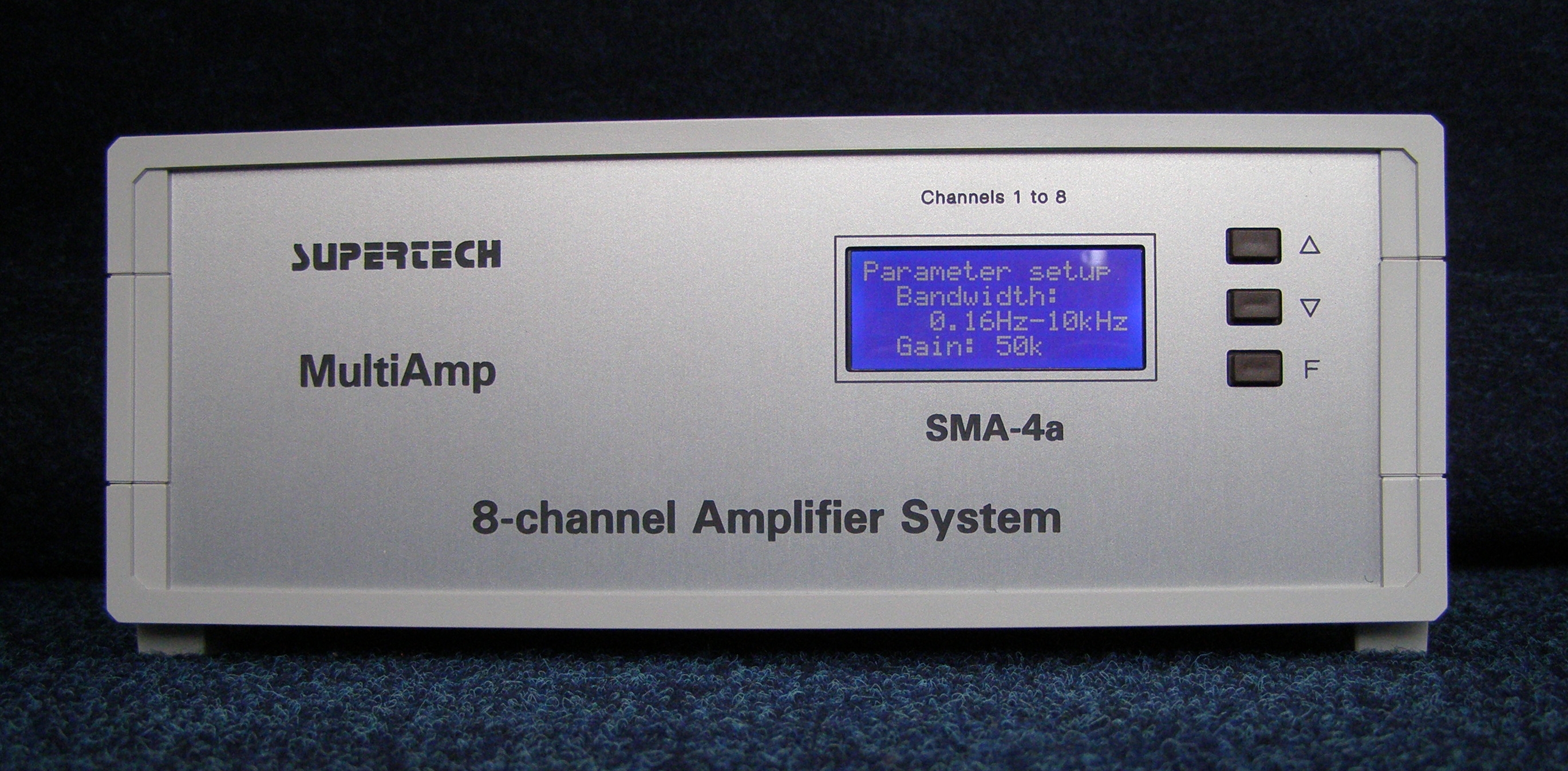
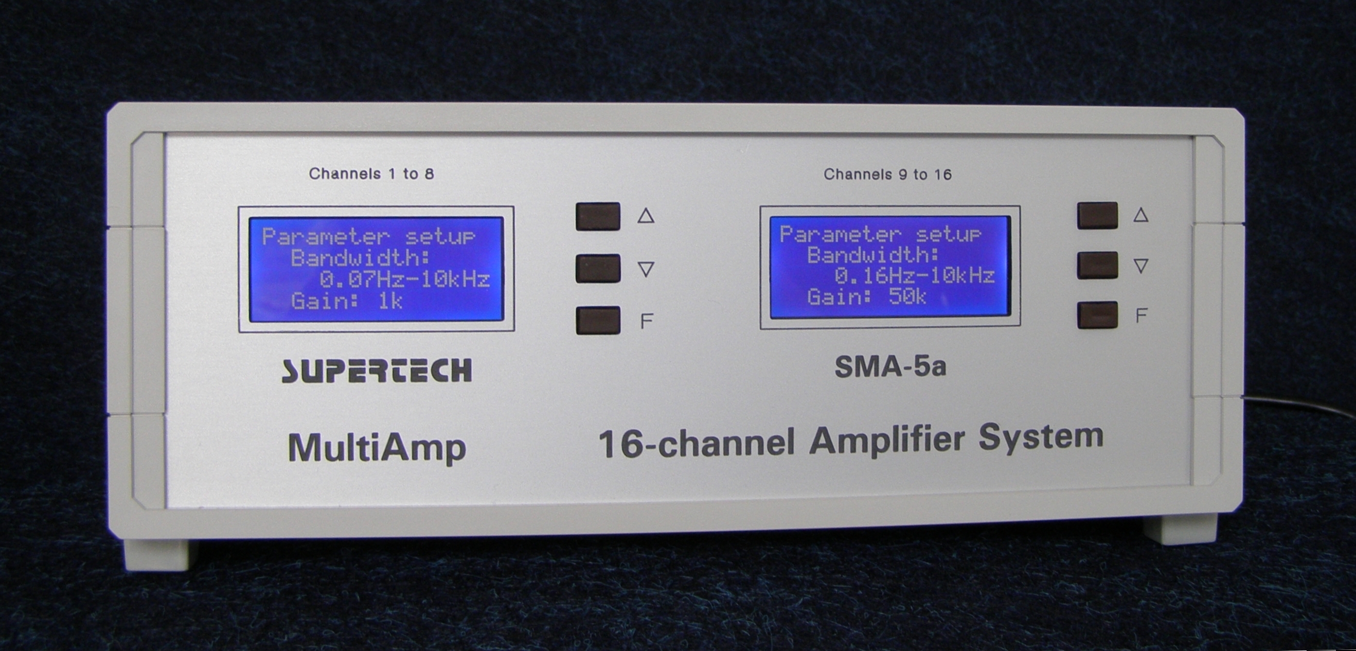
The number of the amplifier channels could be configured in multiples of 8. There were two different amplifier units in our choice. One of the amplifier units was an 8-channel equipment and the other amplifier unit was a 16-channel equipment, where the 16 channels were divided into two 8-channel parts and they could be programmed independently. The Power Supply unit was a separate equipment. From one Power Supply unit a maximum number of 64 amplifier channels could be powered. Certainly, more than 64 amplifier channels could also be installed in one recording system, but for higher (more than 64) channel numbers, more than one Power Supply unit should have been installed. The following list shows the necessary elements to build a given number of the amplifier channels:
8-channel system: one Power Supply unit and one 8-channel MultiAmp amplifier unit
16-channel system: one Power Supply unit and one 16-channel MultiAmp amplifier unit
32-channel system: one Power Supply unit and two 16-channel MultiAmp amplifier units
64-channel system: one Power Supply unit and four 16-channel MultiAmp amplifier units
In the pictures you can see the building bricks of the MultiAmp system: Power Supply, 8-channel amplifier unit and 16-channel amplifier unit.
 Click on the picture to get it in full size
MultiAmp was a programmable amplifier, but it had no sampling circuits in the signal path at all. In other words, it was controlled by a built-in microcontroller or a remote computer, but it had got only high-performance, low noise, low distortion analogue amplifier circuits. This feature was indispensable when the researcher used averaging technique to process the output signals of the amplifier. The internal microcontroller and the optional digital port (which offered remote control capability from a PC) were optically isolated from the amplifier stages. This way we could connect all the advantages of the high accuracy analogue amplifier circuits and easy usage of digital control.
Technical Data
In the MultiAmp system the High Pass Filter had got 4 possible positions, and the Gain had got 8 possible positions. The Low Pass Filter was fixed to 8 kHz in the analog circuitry by default. Certainly MultiAmp was available with other Low Pass filter setting upon request, as well. The actual High Pass Filter and Gain values, realized during the manufacturing process were orderable with the default parameters, but they could be requested with special values, to meet any special requirements, as well. The default values of the Filter and Gain sections were the following.
| High Pass Filter | Low Pass Filter | Gain |
| 0.0126 Hz (12.64 s) | fixed to 8 kHz | 200 |
| 0.16 Hz (1 s) | 500 | |
| 1 Hz | 1,000 | |
| 100 Hz | 2,000 | |
| 5,000 | ||
| 10,000 | ||
| 20,000 | ||
| 50,000 |
Headstages of MultiAmp
 Click on the picture to get it in full size
We offered 8-channel monopolar (single-ended) and 8-channel differential headstages for MultiAmp in our standard product choice. There were some applications, where the most important aspect was the size of the headstage (e.g. freely moving mice and neonatal rats). For such applications we have developed 8-channel and 16-channel interfaces to connect specialized 3-rd party headstages to the MultiAmp system.
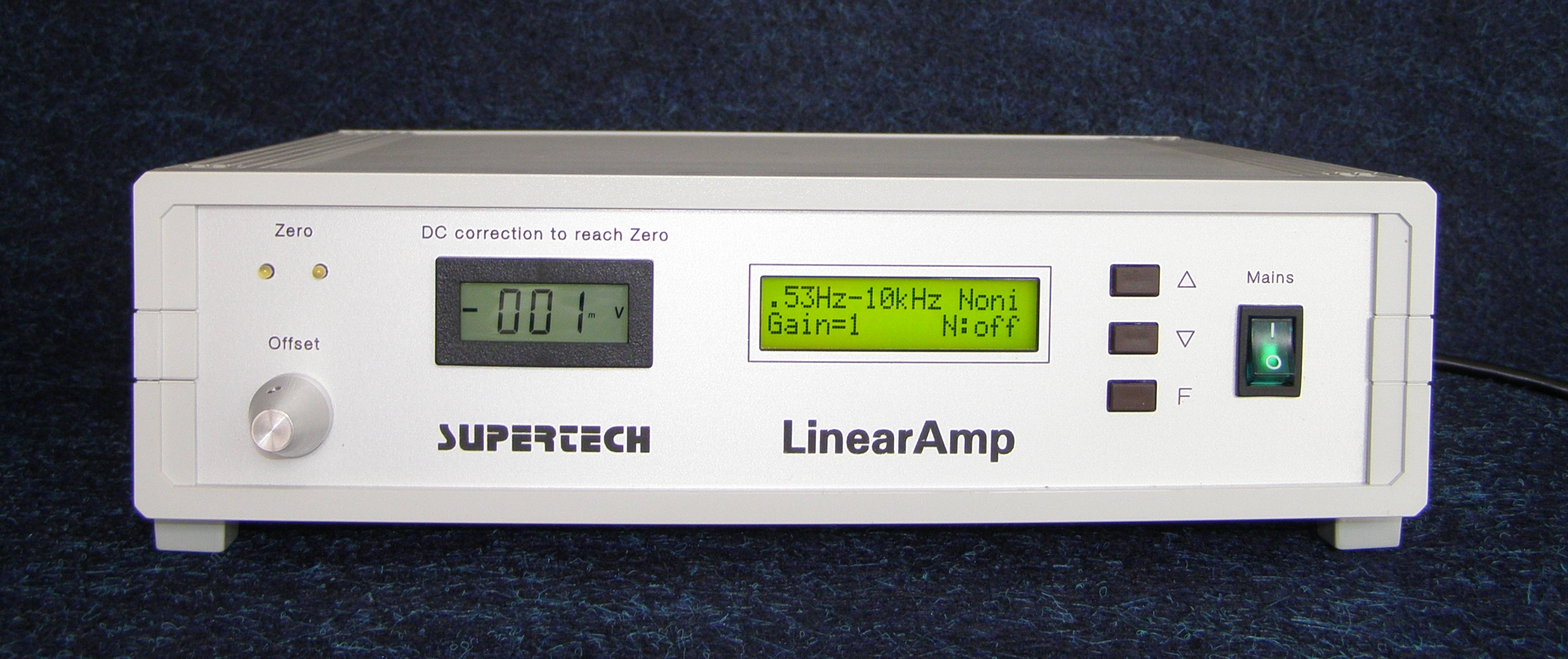
LinearAmp V.4 Signal Conditioner Amplifier
In the past there were three different amplifier systems (BioAmp, MultiAmp and LinearAmp) in our product choice, because the three product lines were optimized for different application fields. BioAmp DC is an up-to-date, highlighted product group of Supertech Instruments for many years, even until now. MultiAmp and LinearAmp families have been retired. This paragraph describes the LinearAmp amplifier family.
LinearAmp amplifier was optimized for high-precision signal conditioning and recording tasks in electrophysiology. It survived four versions under continuous development.
 Click on the picture to get it in full size
Technical Data
The most sophisticated feature of LinearAmp was its Low Pass Filter. The Low Pass filter circuit was an 8-pole, Bessel-type filter with linear phase response. This special, high quality Low Pass Filter was necessary to realize the anti-aliasing function, which is indispensable before the analogue to digital conversion.
In LinearAmp the High Pass Filter, the Low Pass Filter and the Gain had got 8 possible positions. The default values for the Filter and Gain sections are listed below.
| High Pass Filter | Low Pass Filter | Gain |
| DC (0 Hz) | 100 Hz | 0.5 |
| 0.16 Hz (1 s) | 200 Hz | 1 |
| 0.53 Hz (0.3 s) | 500 Hz | 2 |
| 1.6 Hz (0.1 s) | 1 kHz | 5 |
| 5.3 Hz (0.03 s) | 2 kHz | 10 |
| 10 Hz | 5 kHz | 20 |
| 30 Hz | 10 kHz | 50 |
| 100 Hz | 20 kHz | 100 |
In every amplifier channel there was a dedicated DC offset correction circuit, even in a multi-channel system. The voltage range of the offset correction was +/- 200 mV, with 0.1 mV of resolution. There were two different options for the offset correction circuit. One of them was the analogue version with a 10-turn helical potentiometer and a digital voltmeter on the front of the equipment. That is what you can see in the picture above. The other version was the digital realization of the same task as a separated microcontroller, dealing with the numerical control of the offset voltage. This digital offset correction method is currently used in BioAmp DC amplifier system. You can read its detailed description in the
The Notch Filter (hum noise filter) of the LinearAmp was tuned to 50 Hz (or optionally to 60 Hz). The Notch Filter could be switched on and off in the software running on the front plate microcontrollers. The rejection ratio of the Notch Filter on its central frequency was 40 dB.
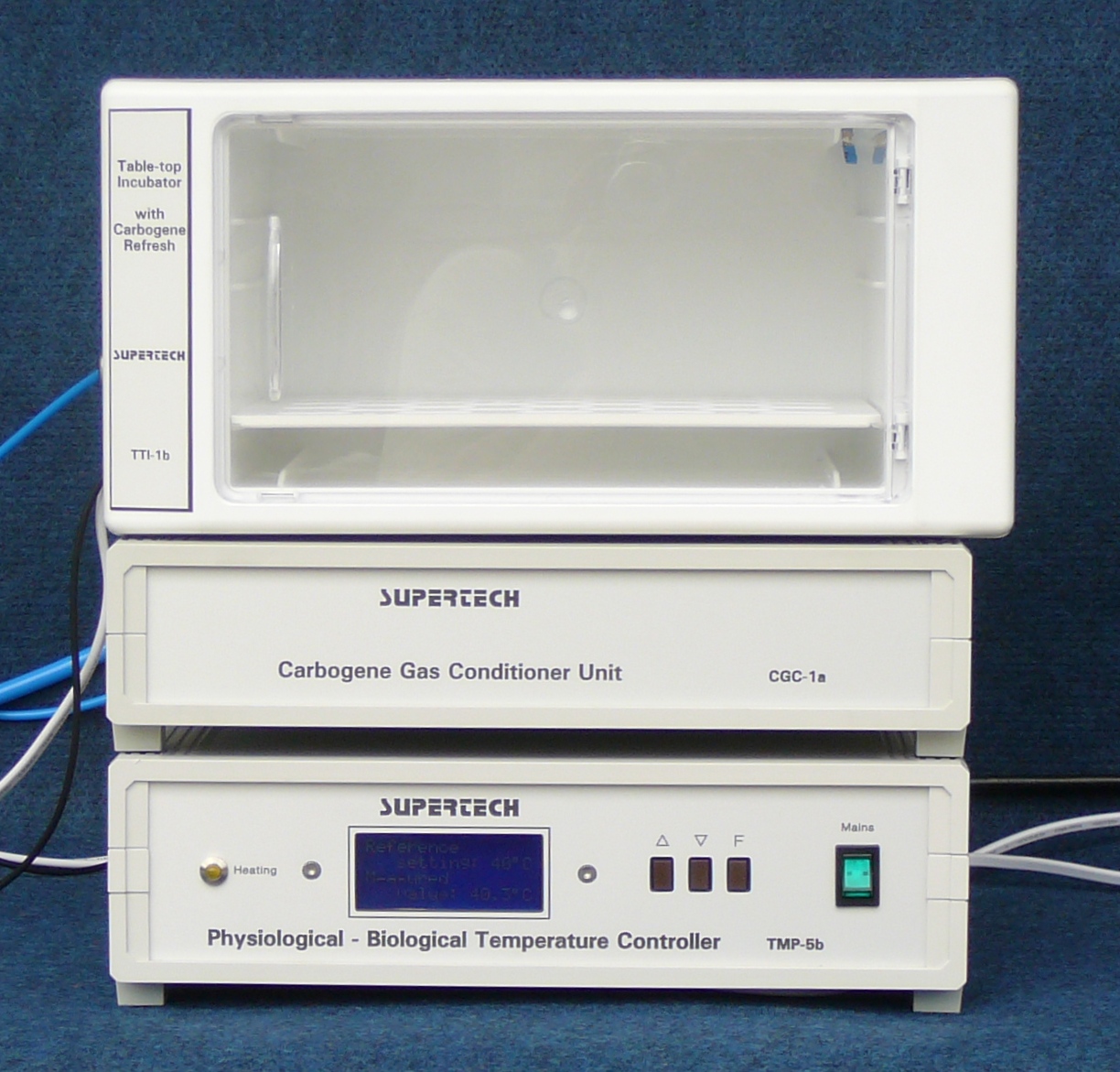
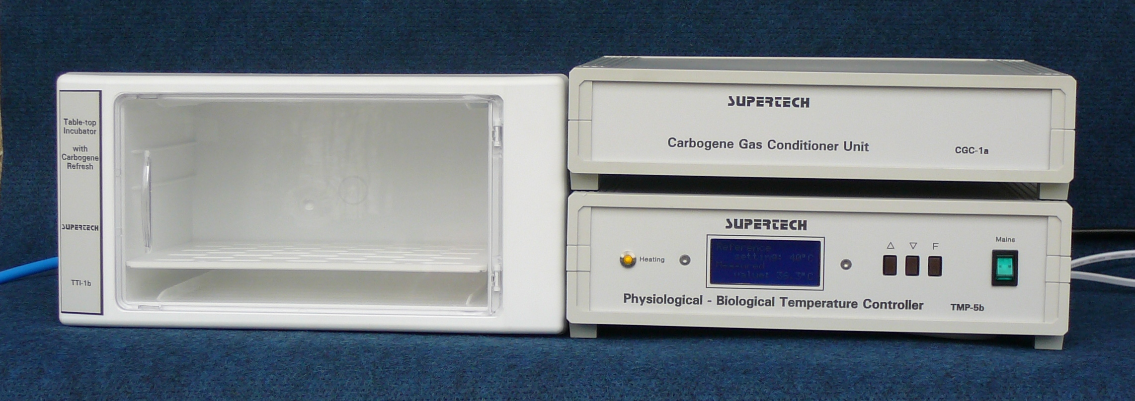
Table-top Incubator
This equipment was developed to compete with the little table-top incubators. The internal temperature of the incubator was regulated by a Physiological - Biological Temperature Controller with the accuracy of 0.5 Centigrade. The internal atmosphere was controlled by a Carbogene Gas Conditioner Unit. We have completed the prototype development process perfectly with promising results. The prototypes became ready, but unfortunately the manufacturing process has never been started.

 Click on the picture to get it in full size
Original, Fine Adjustable Version of the Mouse and Neonatal Rat Stereotaxic Frame Adaptor
The Mouse and Neonatal Rat Stereotaxic Frame Adaptor has been developed to fit mice on any rat sized stereotaxic instruments. According to this approach, this was not a complete stereotaxic device, but a precise fixing adaptor especially for small mice.
Technical Innovations
The worldwide patent procedure to protect the Mouse and Neonatal Rat Stereotaxic Frame Adaptor has been started in 2007.
The vertical positions of the ear bars and tooth holder could be adjusted individually with high accuracy as 0.05 mm. The maximum elevation height was 20 mm to make a firm and easy holding of the skull by fingers during insertation of the mouse into the stereotaxic holder.
The cone of ear bars fittted to the meatus hole. The shape of the ear bar was designed so that it provided a large surface contact to the bone of the skull around the outer ear hole. Thus the cone tip served only for accurate positioning of the ear bar but did not hold the weight of the head. It allowed accurate positioning of the ear bars and firm contact without damaging the skull.
The tooth holder had a hole drilled into the tooth holder bar. The end of the hole was close to the nose and it served the application of Halothane or other inhalation narcotics on mouse to reduce the risk of anaesthesia.
Tooth holders were designed so that a 2 mm lateral movement of the teeth prevented torsion or damage of the scull during centring the head.
The stereotaxic adaptor had a body support block with a slit at the front for nose down surgery. The block could be replaced by a body temperature controller heating pad. After fixation of the head the supporting block could be inserted under the body to keep the animal in a comfortable position.
The Mouse and Neonatal Rat Stereotaxic Frame Adaptor was attached to the rat stereotaxic frame so that electrode positioner stands could be attached to both sides of the frame allowing use of two positioners simultaneously.


 Click on the picture to get it in full size
You can see the most up to date, currently manufactured version of the Mouse and Neonatal Rat Stereotaxic Frame Adaptor on the respective product description page.
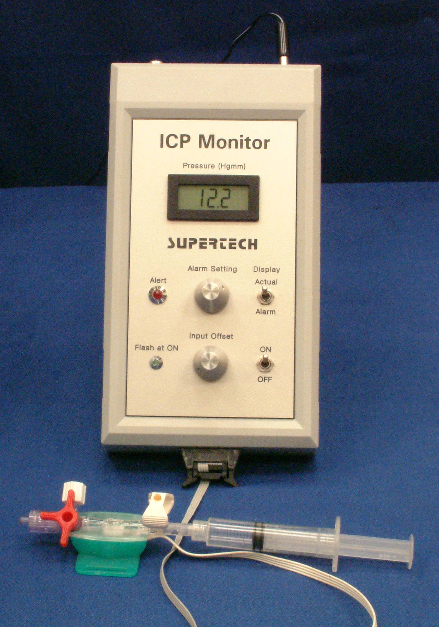
Intra-Cranial Pressure Monitor with Alarm Function (ICP Monitor)
The application field of the ICP Monitor was intensive care in neurosurgery. ICP Monitor was a portable, battery-powered equipment. It had been built in a small plastic case, so it could be used anywhere, even during the transportation of the human patient. This was the main goal of its development process. The standard intensive care monitors are usually not portable equipments. Especially in the neurosurgery there is a very important requirement. The bleeding in the skull must be detected as early as possible, because the life of the patient depends on minutes in such an emergency situation. ICP Monitor was optimized especially for this purpose. It generated an alarm signal in very early phase of the increasing of the intra-cranial pressure. This equipment was manufactured only in a pilot series. It had not generated any profit for Supertech Instruments, but undoubtedly this was our most beneficial product, because it had saved several human lives!
 Click on the picture to get it in full size
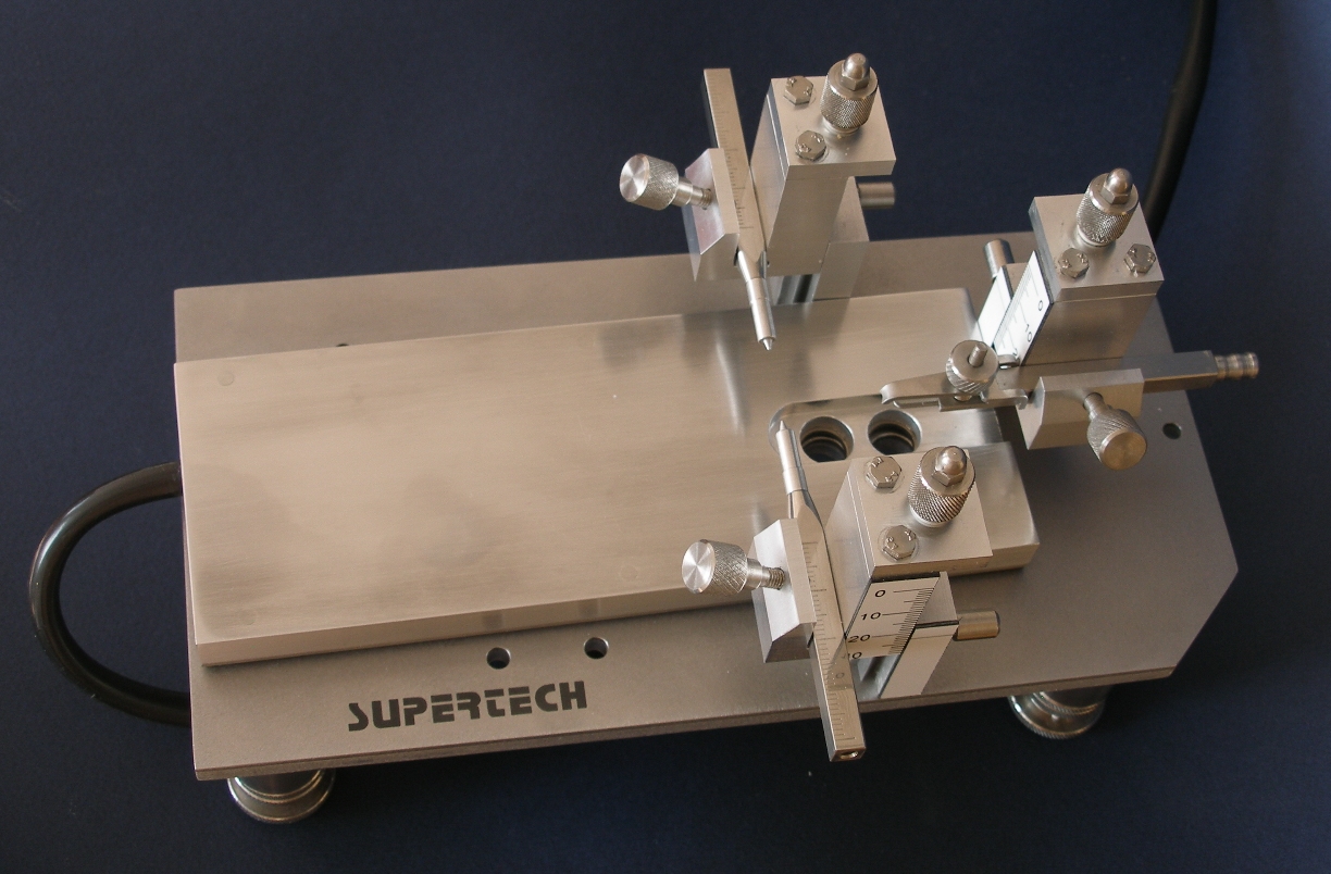
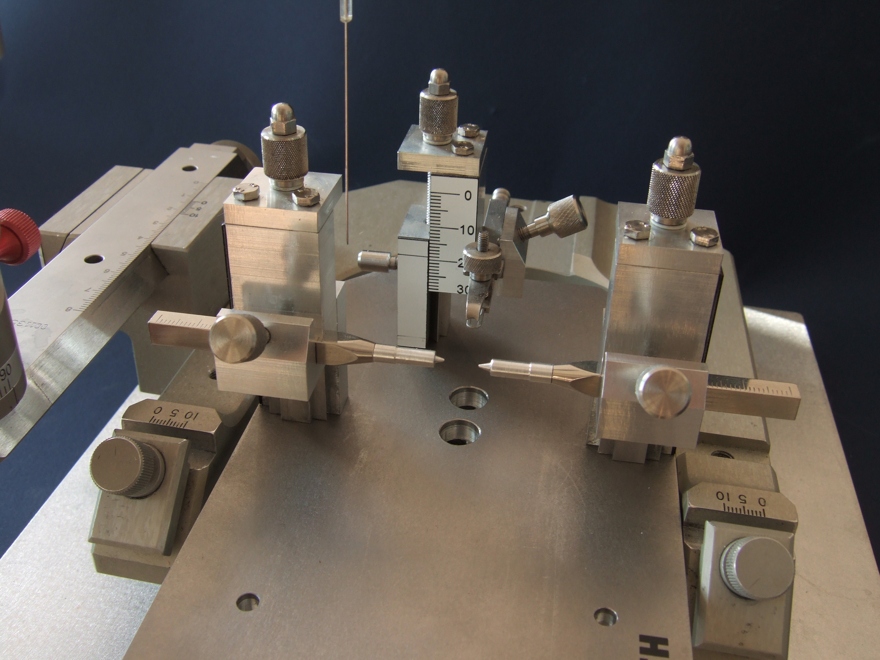
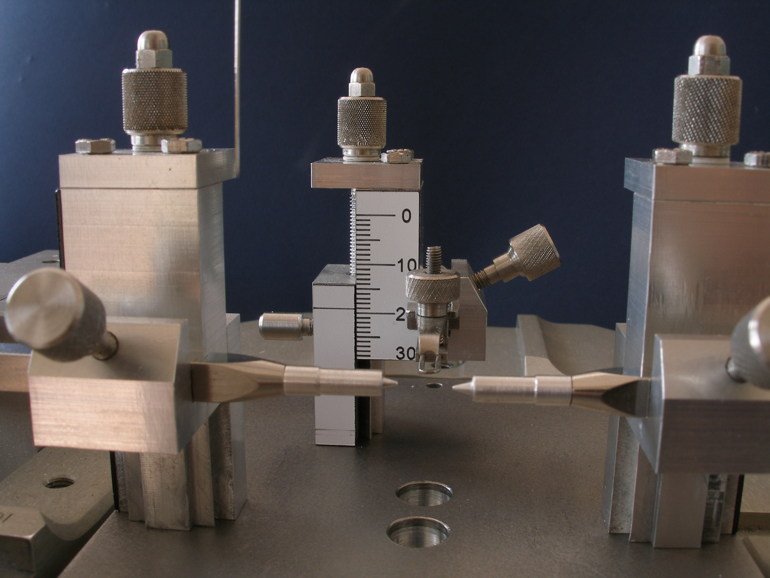
Spine (Back Bone) Holder for Rat
In the pictures below you can see our retired, high precision spine (back bone) holder model. The conical nose holder and the ear bars were optional accessories, they could be removed if the experimental situation did not require them. The screws holding the base plate, the back bone tweezers and the basement of the micromanipulator could be assembled on any side of the equipment.
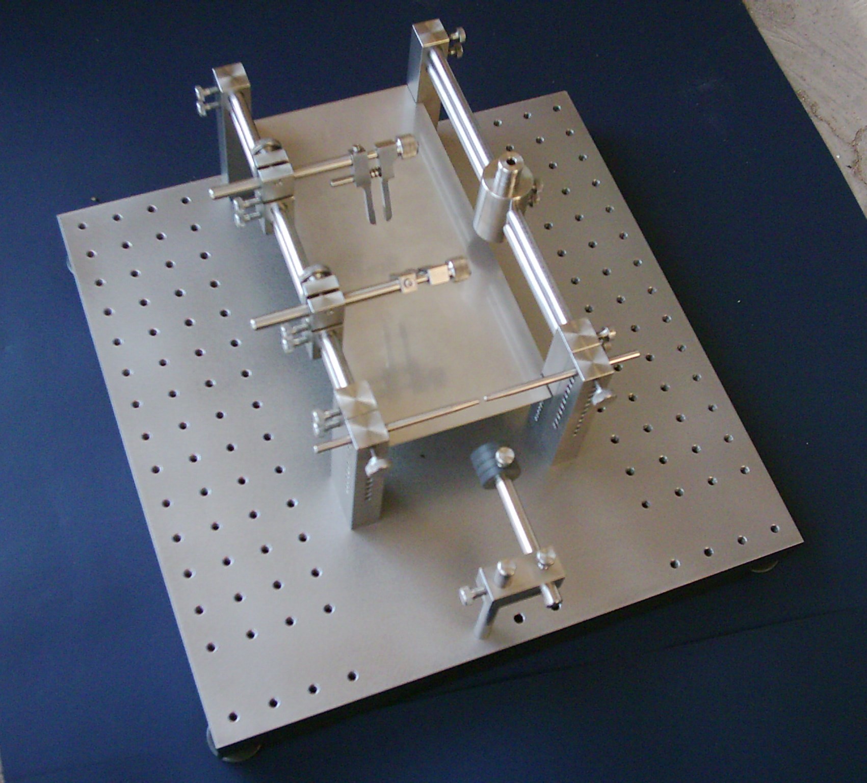
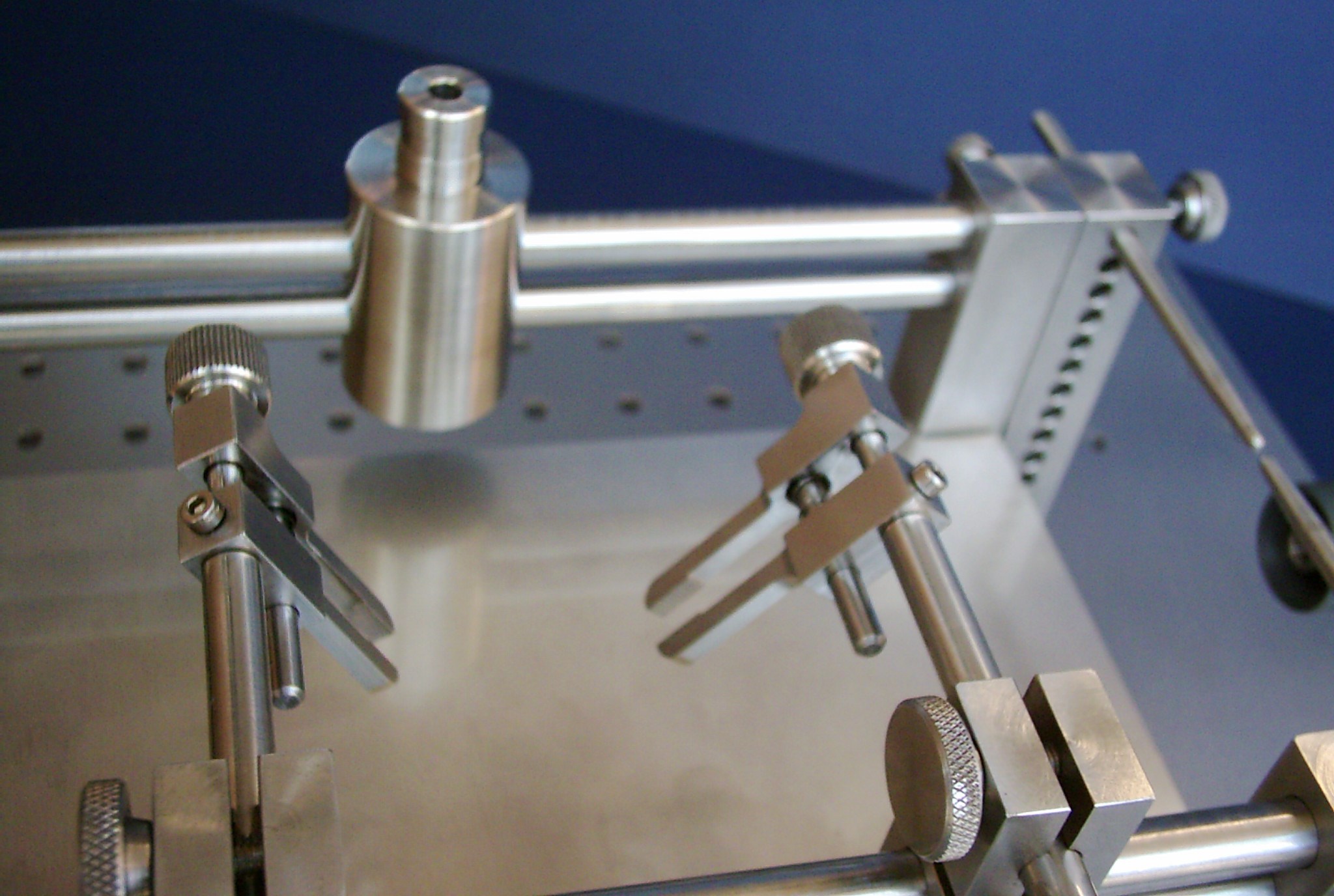 Click on the picture to get it in full size
IonFlow Pro Human Iontophoretic Equipment V.3
Ionophoresis gave a brand new way to pass medicines and other effective substances to the human body. The iontophoretic technique offered a large scope in medical practice, because special pastilles, pills and solutions are manufactured for this purpose. From these special materials the effective substances can be passed with ionophoresis instead of hypodermic needle. The result is: there is NO PAIN of injection any more. IonFlow Pro was designed specifically for cosmetic and all general human medical applications.
Four important fields of applications of IonFlow Pro equipments are listed below as examples:
• Painless cures in cosmetics
• Passing of anodynes into joints (sportsmen for instance)
• Painless cure of Lymph Oedema
• Reduction of thickness of the fat layer under the skin
Technical Data
Output current: 0 - 8 mA, or 0 - 16 mA (in 10 µA steps)
Supply source: 4 kV isolated mains power supply
Compliance voltage: 75 V
Automatic built-in diagnostic and security protection algorithms
 Click on the picture to get it in full size
IonFlow Modular Iontophoretic Equipment for Multi-barrel Electrodes V.2
IonFlow Modular equipments were multi-channel iontophoretic equipments designed specifically for researchers using multi-barrel microelectrodes. The number of the iontophoretic channels could be optimized for the actual experiment. The system could be configured up to 8 channels (plus the compensating channel). Every applicator channel were located in a separated equipment box. The boxes could be put on each other. This way the system could be mounted as a "tower". There was a special cable, which connected the elements of the "tower" to form one synchronized equipment system. This way it was not necessary to buy more number of channels than it was really necessary (exactly as the number of barrels of the electrode). If the number of the barrels used in the experiment was increased, the system could be expanded very easily. The only task was to put one more "level" on the top of the "tower" and to connect it to the system. The power supply of the IonFlow Modular was a highly sophisticated floating power supply, because this system was always used in microelectrode environments, where the protection against the hum noise was essential. Furthermore, the distance between the recording electrode and the iontophoretic electrodes were extremely small on the multi-barrel electrodes. The compensating channel had got a special function. Its task was to produce a current with opposite polarity, but the same amount as the algebraic sum of the iontophoretic applicator currents of the channels. This compensation of currents to zero avoided the excitation effect for the cells. In every multi-channel system only one compensating channel was necessary to be installed. The compliance voltage was +/- 40 V in this equipment. The compensating channel worked automatically according to the commands received from the iontophoretic channels.
 Click on the picture to get it in full size
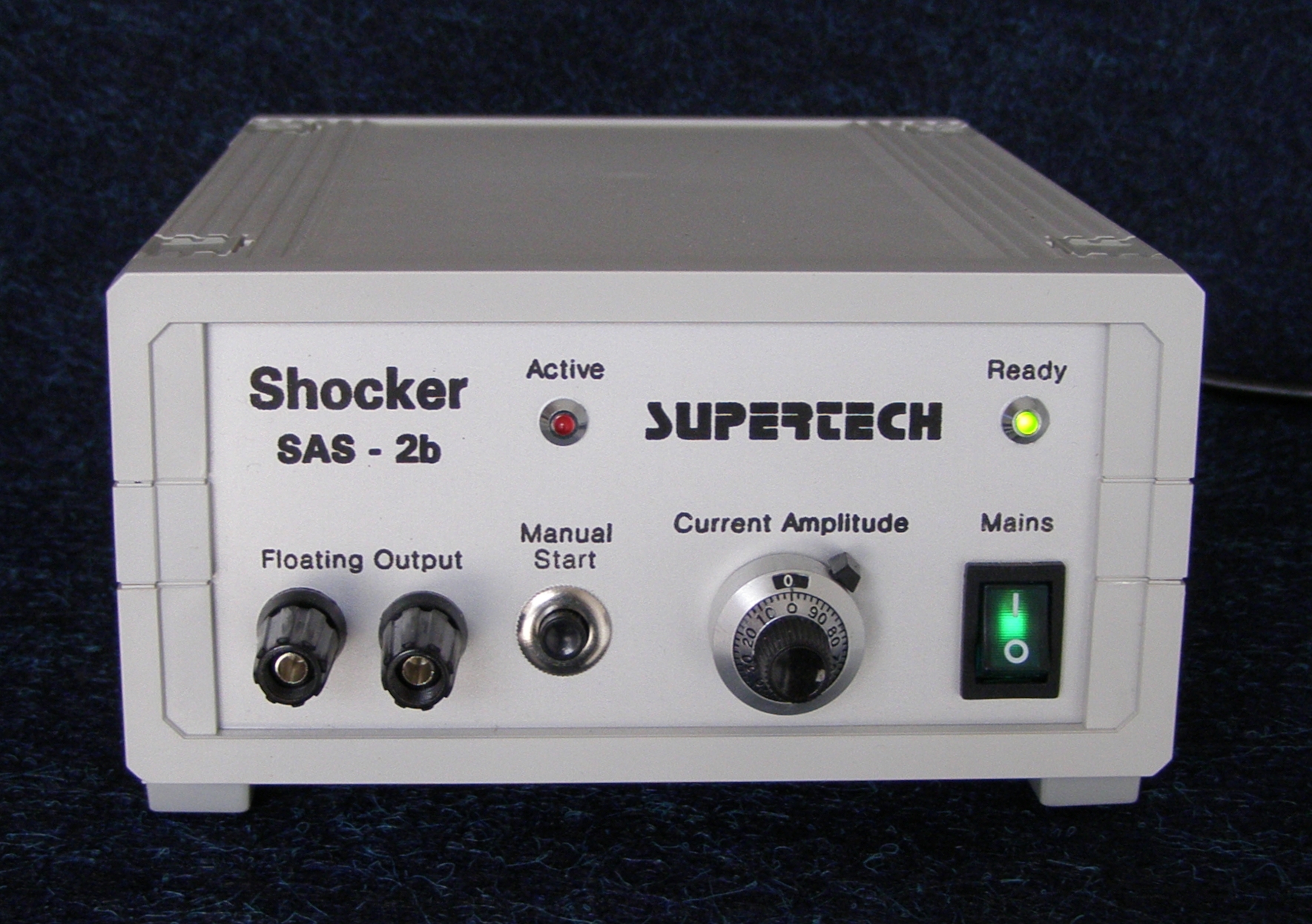
AC Shocker
 Click on the picture to get it in full size
AC Shocker SAS-2b was a simplified, handy lab animal shocker. Its internal circuitry was based on a constant current generator operating on the mains frequency. The current generator was simplified, but the safety level of this equipment was as good as of the DC Shocker. AC Shocker SAS-2b had got three security isolation barriers. Its output was totally isolated (floating output) for the sake of the safety for the operator and the subject. Furthermore it had isolation from other electronic devices such as physiological stimulators that may be in use concurrently. Isolation was performed by using an isolated power supply transformer along with 4 kV optical isolation of the inputs from the control equipment.
Specifications / Technical Data
AC current generator at the output
The output waveform is bipolar sine wave
Current range at the output: 0.05 to 2 mA
Output load range: 0 (shortcut) to open circuit (any load is allowed)
Compliance (open circuit) voltage: 180 V AC RMS
Working (shocking) frequency: 50 Hz or 60 Hz (equals to the mains frequency)
![]()
![]()
![]()
![]()
![]()
![]()
![]()
![]()
Copyright @ Supertech Instruments - since 1991