
![]()
![]()
![]()
![]()
![]()
![]()
![]()
![]()
Engineering Creativity for Neuroscience
Behavioral Physiology of Laboratory Animals
Modular Behavioral System
Complete, integrated hardware/software system to study the learning, memory and behavioral activity of the experimental animals. Research of learning and memory requires special data acquisition and control systems with unique peripheral interfaces to interact with the behaving laboratory animals. Modular Behavioral System has been designed for this aim. In this description both words "module" and "unit" are used as synonyms, because their meaning is the same in this context: a detachable part of the system. Modular Behavioral System consists of a power supply module, a microcontroller-based system controller unit, different peripheral control units and a Windows-based behavioral control program.
Behavioral physiology requires great versatility and variability of the measuring equipments, because the experimental paradigms are changed frequently. The most important aspect was the flexibility in the development process of the Modular Behavioral System. Its base feature is the modularity. The hardware configuration can be rearranged in minutes by the researcher. On the hardware side the system controller unit can process up to 12 event control signals simultaneously. In the hardware the number of the input and output signals is not restricted, only their total number is limited to 12.
“Automated Stimulus Control” program offers a simple but powerful graphical interface to design any interactive behavioral task and provides the sampling, collection and recording of the experimental data. The individual setup configurations can be saved and loaded. “Automated Stimulus Control” program is a subject of continuous development. The currently available v1.5 version offers four output channels, one of them is a sound channel. Two output channels are slow with 1 sec of time resolution. Two output channels are fast with 1 msec of time resolution. The timing of the channels are strictly synchronized to each other.
The peripheral units of the Modular Behavioral System send or receive the event control signals from/to the experimental environment. On the one hand the peripheral control units communicate with the system controller via an internal system bus. On the other hand the peripheral control modules communicate with the external peripheral devices on standard TTL level. This way (using TTL level at the inputs and outputs) any third-party peripheral circuit and any newly developed peripheral equipment can be connected to the Modular Behavioral System any time.

 Click on the picture to get it in full size
The complete User Manual of the Modular Behavioral System is available for download.
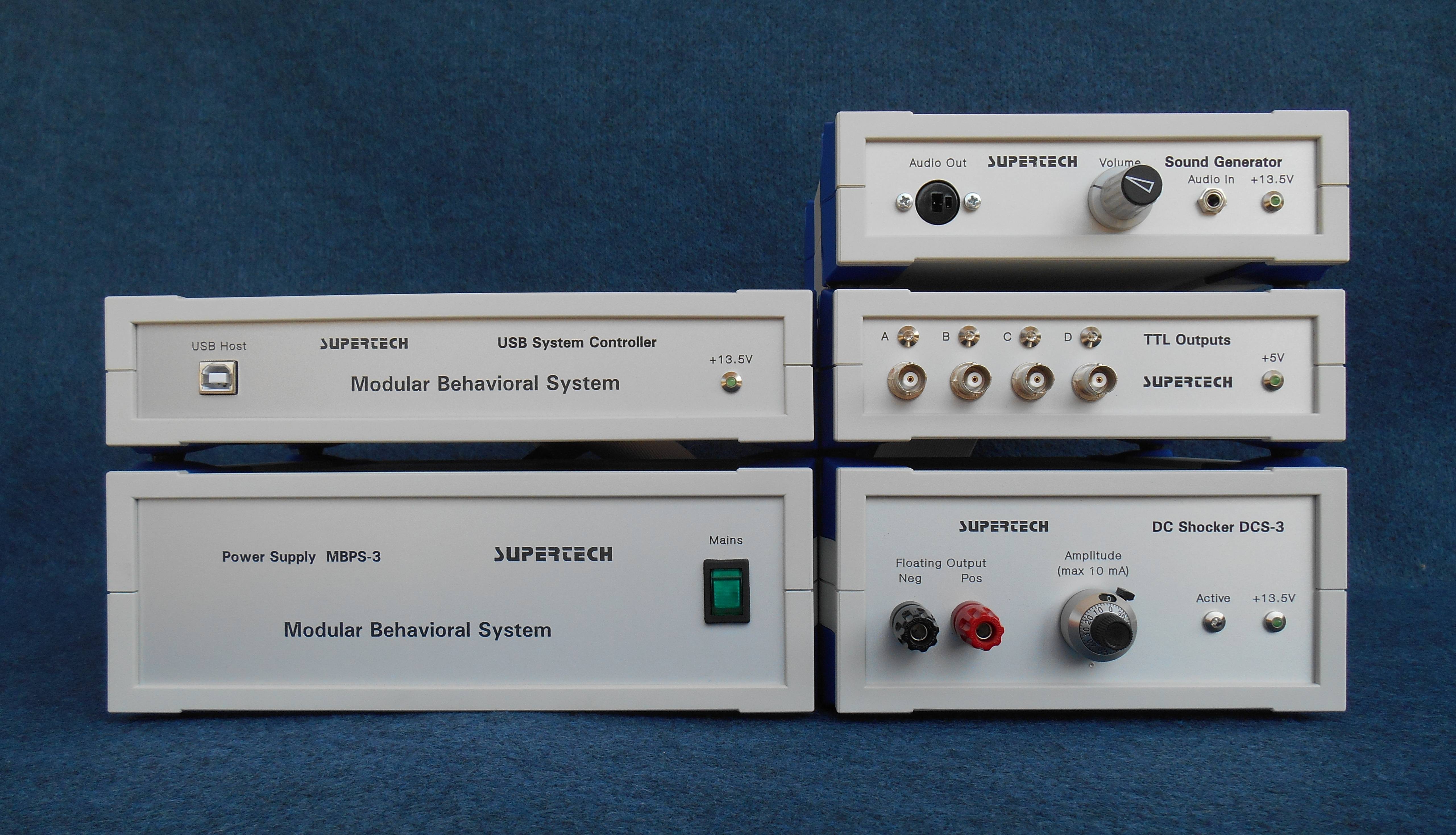
Parts of the Modular Behavioral System
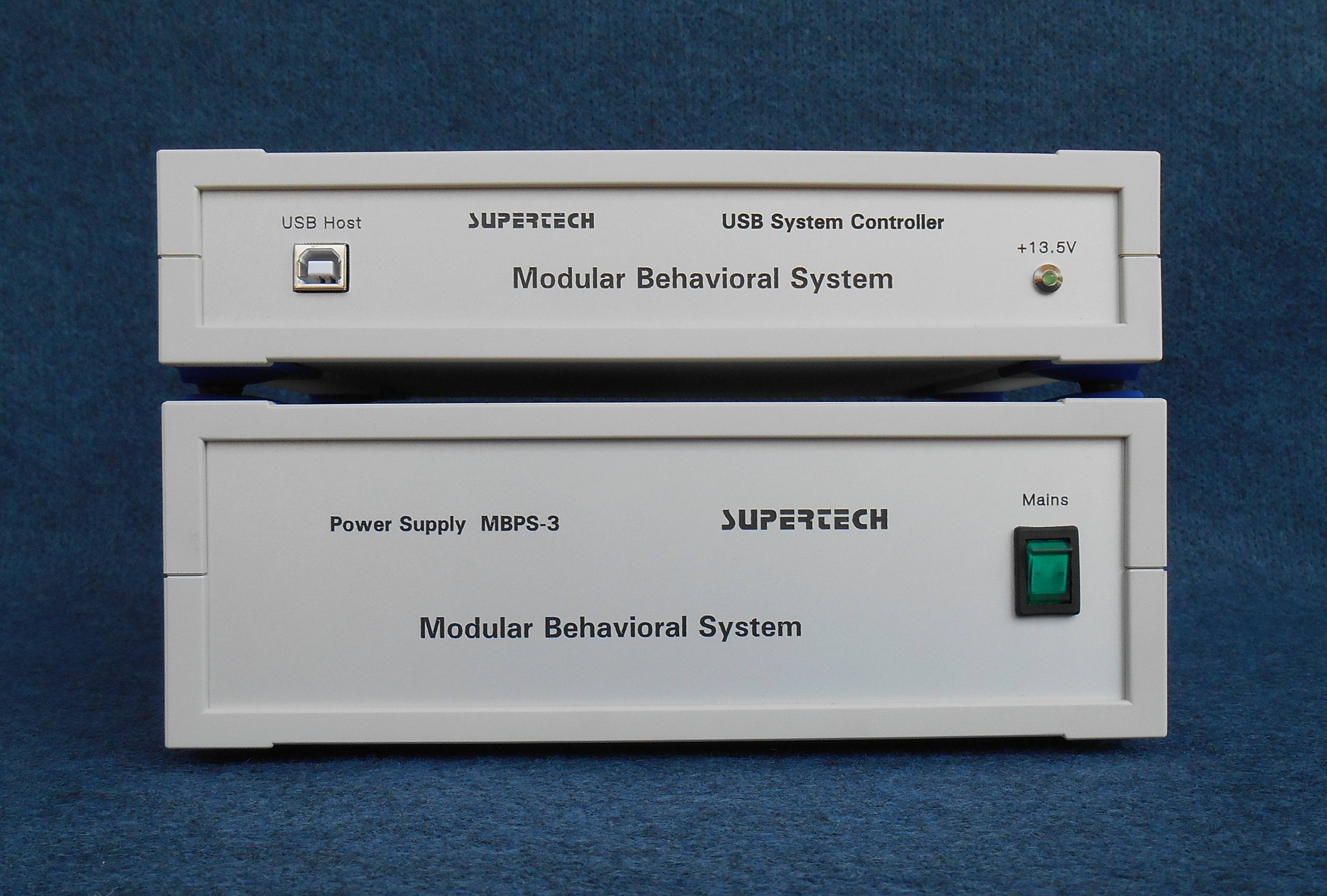
The number and type of the peripheral units in the Modular Behavioral System is flexible. They can be ordered independently of each other, according to the actual requirements of the experimental paradigm. There are three base components, which should always be involved in every system. They are the Power Supply Module MBPS-3, the 12-bit USB System Controller and the control program.
Currently the following hardware components of the Modular Behavioral System are available. They are described in detail on this page below.
• Power Supply Module MBPS-3
• 12-bit USB System Controller MBSC-1
• 4-channel TTL Input Control Module MBTTLI-1
• 4-channel TTL Output Control Module MBTTLO-1
• Sound Generator End-stage MBSG-1
• DC Shocker DCS-4 (1-channel, floating, isolated)
• DC Shocker Controller PDC-2 (option, if MBSC-1 is not used)
Power Supply Module MBPS-3
Power Supply Module provides the supply voltages for the components of the Modular Behavioral System. This unit establishes very accurate supply voltages with precise load and noise regulation. On the front plates of the peripheral components of the system there are indicator LEDs to show the presence of the supply voltages of the modules.
Power Supply Module MBPS-3 is available in 115 VAC or in 230 VAC mains voltage version.
12-bit USB System Controller MBSC-0
Click on the picture to get it in full size
This equipment is an intelligent unit based on a high-end AVR microcontroller operated by a built-in firmware. This unit is an interface between the control program running on the PC and the peripheral modules of the Modular Behavioral System.
12-bit USB System Controller is connected to the PC via USB. The USB port is the communication channel between the PC and the firmware in the 12-bit USB System Controller.
12-bit USB System Controller is the origin, the master of the digital input/output lines of the system bus. The system bus consists of 12 digital input/output lines. You can find detailed information about the usage of the digital input/output lines in the User Manual of the Modular Behavioral System.
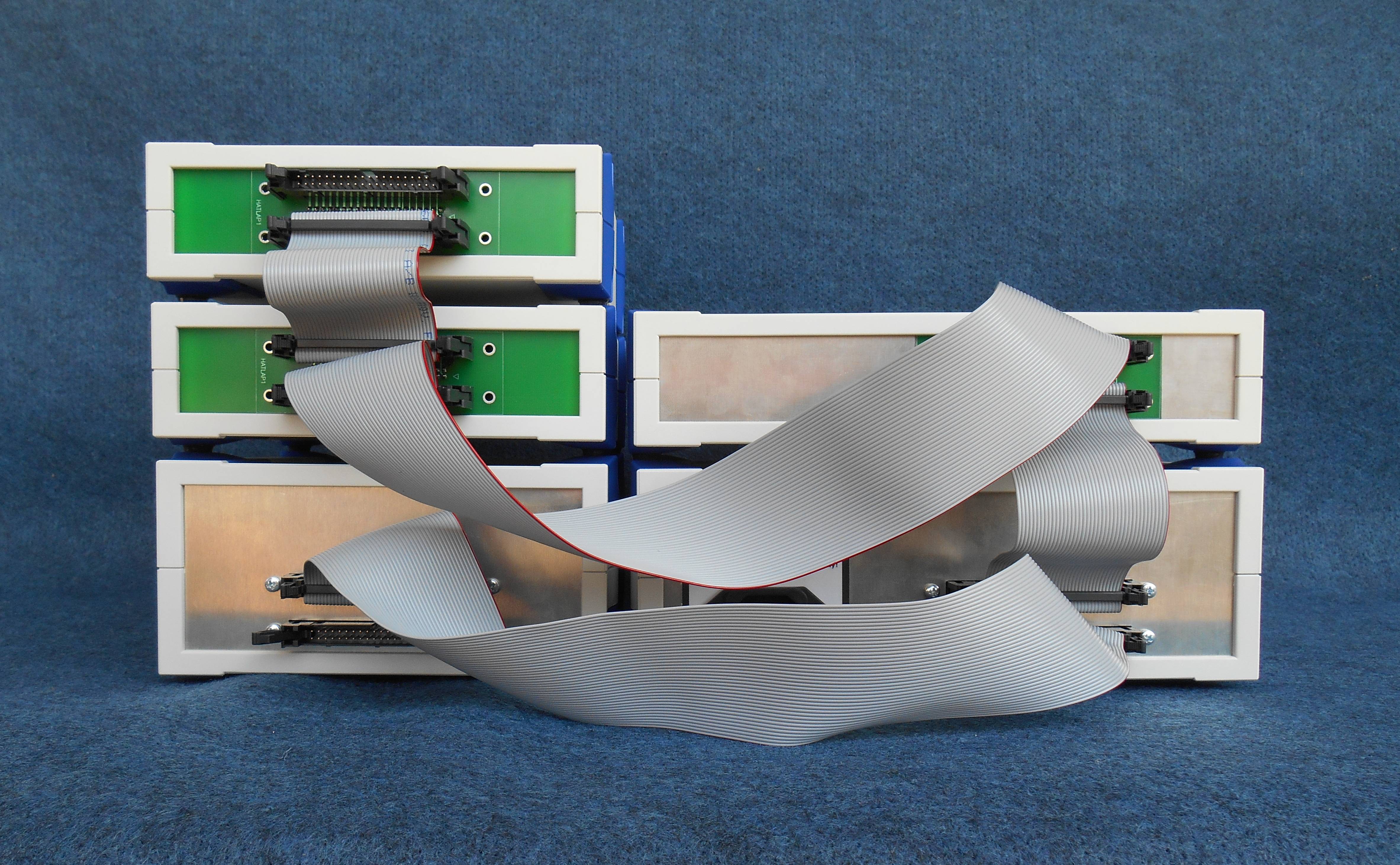
System Bus of the Modular Behavioral System
 Click on the picture to get it in full size
On the back side of every component of the Modular Behavioral System there are two pieces of 40-pin Berg sockets. These two sockets are internally connected parallel. Physically it is the system bus. In the Modular Behavioral System the 40-wire cables are used to connect the functional units (in other word modules) of the system together. Every equipment in the system must be interconnected on the system bus.
On the bottom side of every peripheral module you can find a small window on the enclosure covered with a small plastic plate. If you open the screws of the cover you can find the selector matrix. By the selector matrix you can assign the input/output lines of the 12-bit USB System Controller to the channels of the given peripheral unit. You can find detailed explanation of the assignment of the input/output lines to the peripheral modules in the User Manual of the Modular Behavioral System.
4-channel TTL Input Control Module MBTTLI-0
The four pieces of BNC connectors are the digital inputs of the TTL Input Control Module. They have identifier letters A to D instead of numbers. The reason is that the digital input/output lines of the system bus are numbered. This way they cannot be mixed up during the assignment process of the input/output lines of the 12-bit USB System Controller to the channels of the TTL Input Control Module.
Inputs: TTL / 3.3 V compatible, 0.5 unit-loads
The TTL standard describes the voltage and load specifications of the inputs and outputs of a digital logic system, what is supplied from 5V. Nowadays most of the microcontrollers and digital systems use 3.3V of supply voltage internally. The inputs of the TTL Input Control Module are universal. They are fully compatible with the standard TTL specification. Furthermore they accept the logic levels of the non-standard-TTL 3.3V systems correctly, with optimal noise margins, too.
4-channel TTL Output Control Module MBTTLO-0
 Click on the picture to get it in full size
The four pieces of BNC connectors are the digital outputs of the TTL Output Control Module. They have identifier letters A to D instead of numbers. The reason is that the digital input/output lines of the system bus are numbered. This way they cannot be mixed up during the assignment process of the input/output lines of the 12-bit USB System Controller to the channels of the TTL Output Control Module.
Outputs: TTL compatible, 10 unit-loads capability
Warning! The digital outputs produce standard TTL voltage levels. They must not be connected to the inputs of a 3.3 V digital system directly, because the 3.3 V inputs would be destroyed! There are special voltage translator circuits to solve this incompatibility.
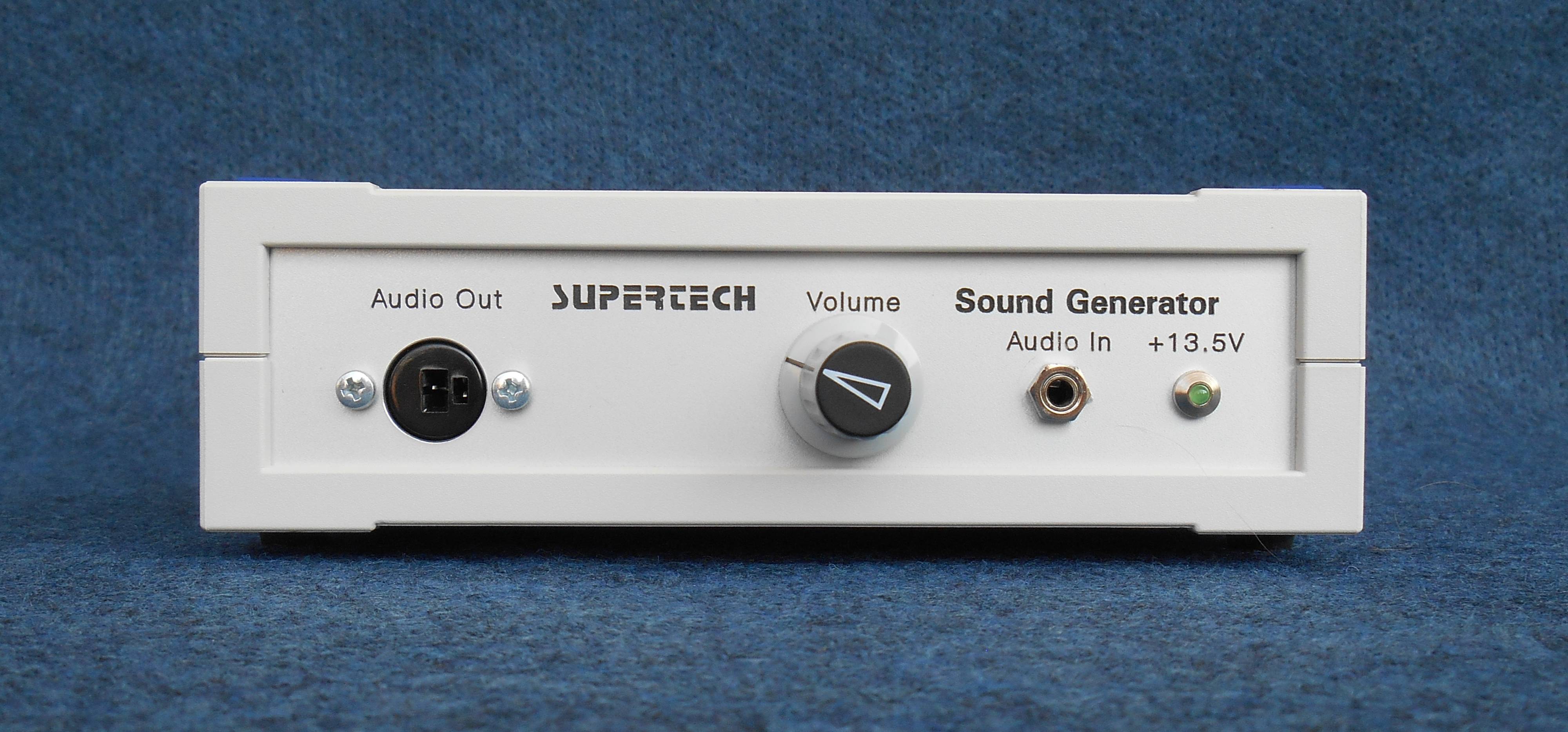
Sound Generator End-stage MBSG-0
Click on the picture to get it in full size
Audio Input of the Sound Generator End-stage is a stereo 3.5 mm jack. This input receives stereo signal from the sound output of the PC. The control program can use the advantage of the stereo sound capability of the PC. On the left and on the right channel two independent sound samples can be generated. After receiving the stereo signal from the PC, they are mixed together in the Sound Generator End-stage and amplified together as a mono signal.
Audio Output of the Sound Generator End-stage is a mono 6.3 mm jack.
Maximum output power (THD=10%): 500 mW
Impedance range of the loudspeaker: 8 – 32 Ohm
Volume control: 10-turn helical potentiometer with scale accuracy of 0.001
The volume control of the Sound Generator End-stage is not usual. The reason, why it was designed such an expensive way was the repeatability. You can calibrate the sound pressure level of the whole acoustic system (source of sound, amplifier and loudspeaker) once and you can reproduce the calibrated situation with the extremely precise scale of the volume control potentiometer any time.
For the Sound Generator End-stage we provide a suitable wideband loudspeaker as an accessory.
DC Shocker DCS-4
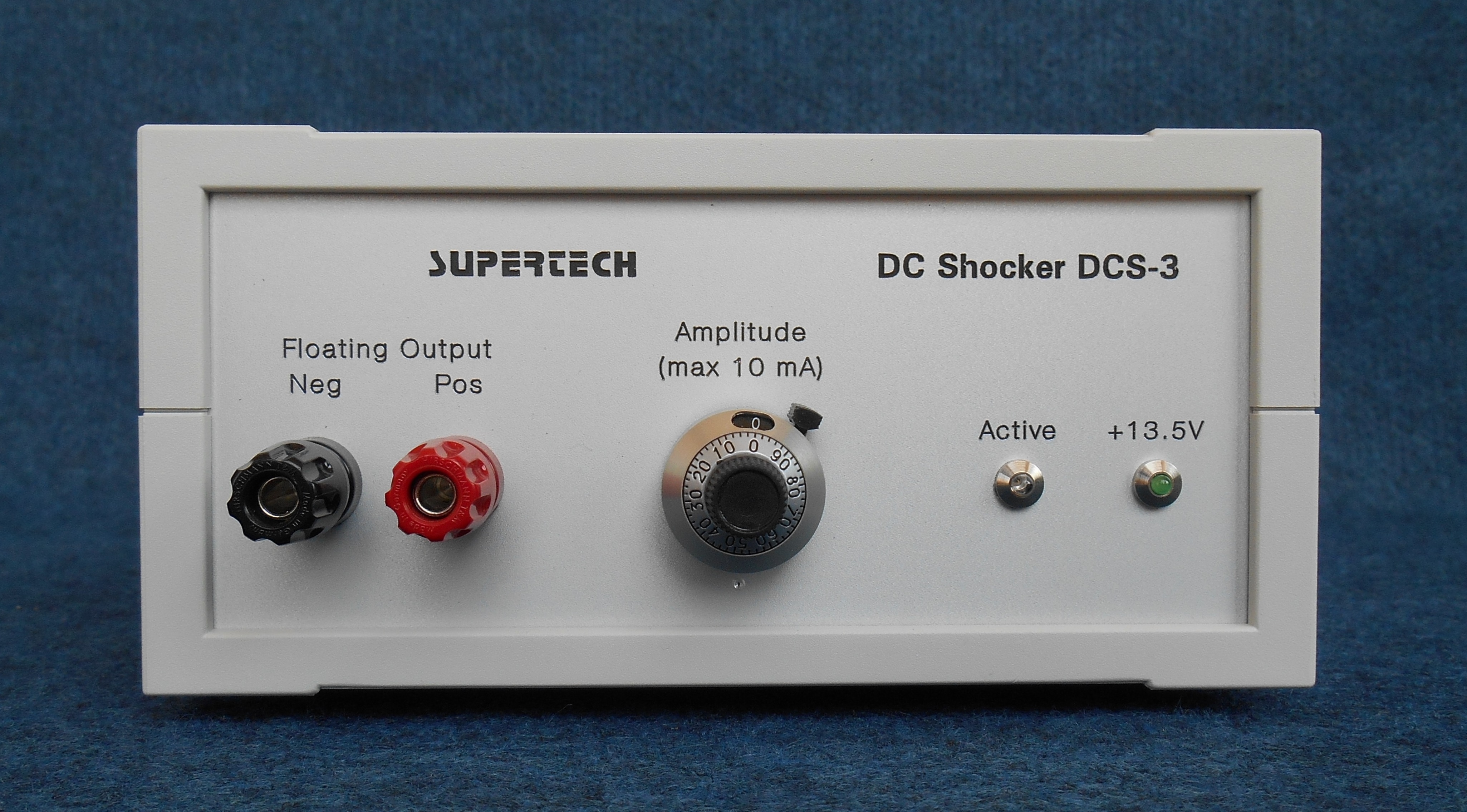 Click on the picture to get it in full size
DC Shocker DCS-4x is a research grade animal shocker. Its internal circuitry is based on a precision and fast feedback regulated constant current generator. This shocker equipment has three security isolation barriers. Its output is totally isolated (floating output) for the sake of the safety for the operator and the subject. Furthermore it has isolation from other electronic devices such as physiological stimulators that may be in use concurrently. Isolation is performed by using an isolated power supply transformer, an additional high voltage isolated floating power supply along with 4 kV optical isolation of the inputs from the control equipment.
The output current range (0 to 10.0 mA) is quite wide to cover nearly every research application. This output current range is suitable even from small mice to huge experimental animals (e.g. sheep, pigs). There is a precise 10-turn helical potentiometer to adjust the output current. It gives a great resolution to fine tune the level of the shocking current. The output circuit of the DC Shocker operates as a two-pole monopolar constant current square wave output.
DC Shocker is manufactured in two versions.
Modular version of DCS-4x: as a part of the Modular Behavioral System. This version has no its own power supply. This version is powered by the Power Supply Module MBPS-3 of the Modular Behavioral System. In this arrangement (in the Modular Behavioral System) the time parameters are provided by the fully digital DC Shocker Controller PDC-x and the constant current source is implemented in the DC Shocker equipment.
Self-powered version of DCS-4x: As stand-alone equipment. This version contains a built-in mains power supply. This version of the DC Shocker can be used as stand-alone equipment, connected to and controlled by any data acquisition system.
The complete User Manual of the DC Shocker DCS-4x is available for download.
Security Rules
The output of the DC Shocker is able to produce extremely large current and voltage in relation to biological objects. From this virtue comes its disadvantage (which is by the way valid for all professional shocker devices): DC Shocker equipment in the case of unprofessional, incautious, or negligent usage can cause life threatening electric shock on the subject, or the person making the experiment (henceforward: the operator). Supertech Instruments manufactures all its products with the most modern protecting and security circuits. However these methods do not protect in the case of errors committed by the operator. Against human errors it is not possible to defend the user with the help of circuitry methods.
DC Shocker equipment is able to apply a maximum 120 V of pulsing DC voltage and 10 mA of pulsing DC current. These data far exceed the life threatening or lethal limits.
The shocking grids are big, free and accessible by hand. Never touch the shocking grid!
There is a much more detailed explanation of the safety rules in the User Manual of the DC Shocker DCS-4x. Please study it carefully before using the equipment!
Specifications / Technical Data
DC constant current generator at the output
Output waveform: monopolar square wave
Range of the output current: 0 to 10.0 mA
Accuracy of the output current: 1 %
Output load range: 0 Ohm (shortcut) to open circuit (any load condition is allowed)
Compliance (open circuit) voltage of the output current generator: 120 V DC
Working (shocking) frequency: 0.0001 Hz to 5 kHz
Minimal output pulse width: 100 microseconds
Maximal output pulse width: unlimited
Supply voltage: 13.5 V +/- 5%. Modular version of the DC Shocker DCS-x is supplied from the MBPS-x Power Supply unit of the Modular Behavioral System.
Manual output current adjustment with a 10-turn helical potentiometer
External TTL control or computer-controlled activity from the Modular Behavioral System (the two control sources may be used together, independently of each other)
Control input: TTL active level is High (over voltage protected, from 2 V to 40 V)
Double security insulation from mains
Double security insulation of output
4 kV opto-isolated TTL control input
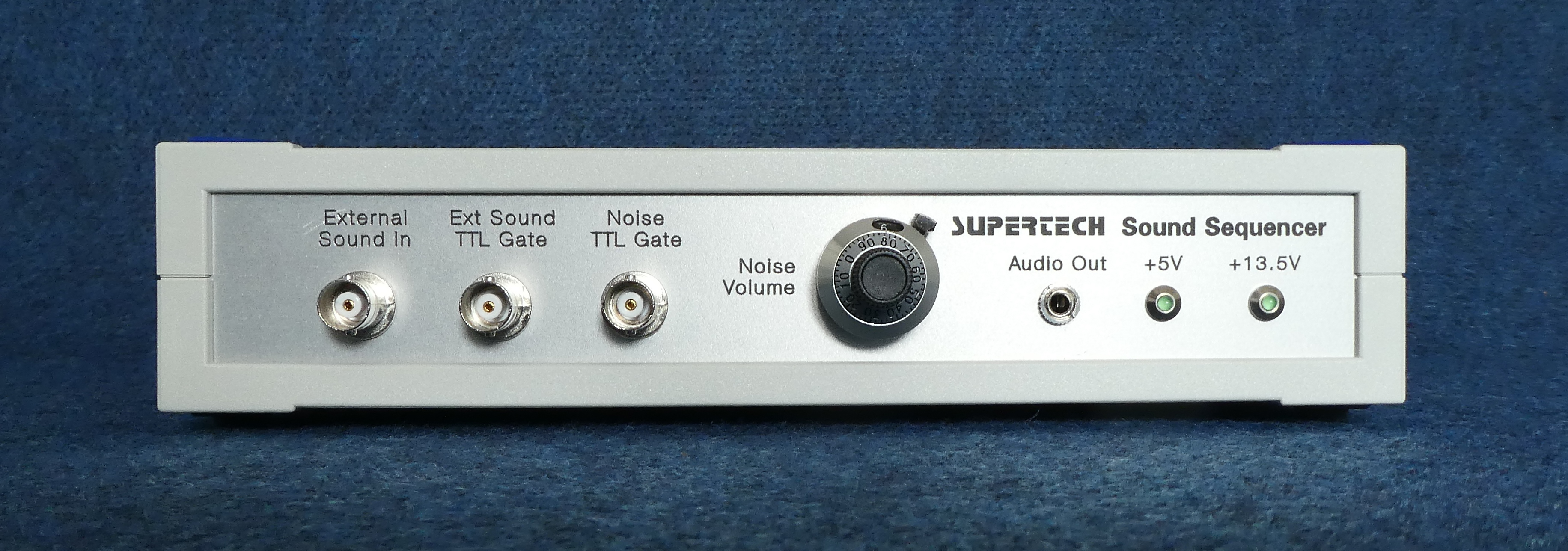
Further Development Example (1)
Until now we have developed the above listed modules for the Modular Behavioral System. Since the research of learning and memory raises new challenges for the scientists day by day, you may not find the appropriate peripheral module for your special task in our actual choice. If the desired unit of yours seems to be interesting for other researchers as well, Supertech Instruments will develop that equipment especially for you. It is our method, how we improve the features of our system. We collect all the notices and feedbacks of our customers, and we implement their (may be your) knowledge into the features of the Modular Behavioral System.
 Click on the picture to get it in full size
Sound Sequencer equipment is demonstrated here as an example. This is a uniquely developed peripheral unit for the Modular Behavioral System. It is a microcontroller-based intelligent device to generate and mix user-defined sound patterns and white noise sequences. This module extends the default sound capability of the Modular Behavioral System.
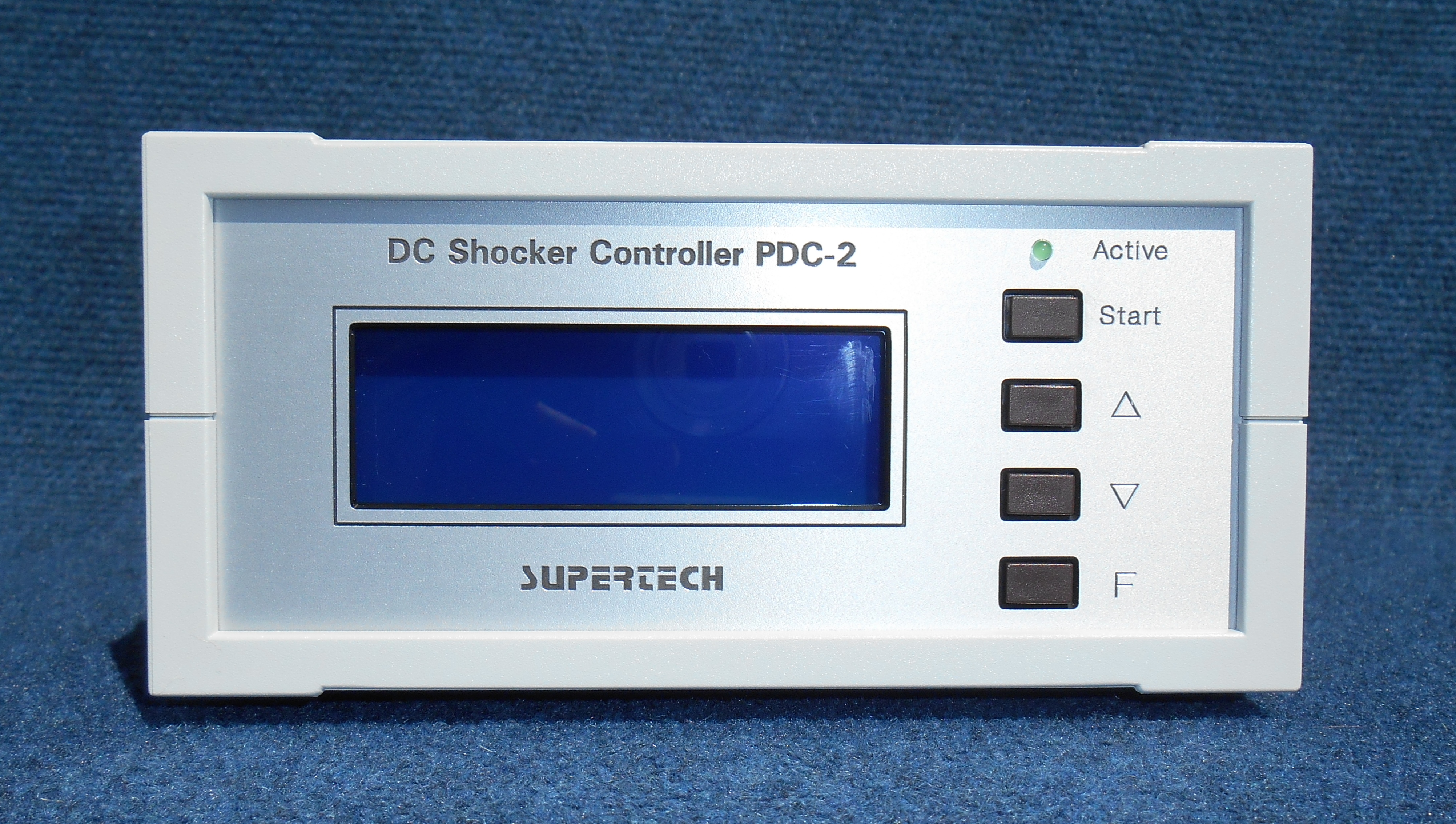
Development Example (2), DC Shocker Controller PDC-2
 Click on the picture to get it in full size
It is an option. This equipment has been developed for that situation if USB System Controller MBSC-1 is not used. If you order a PC controlled system, then you do not need DC Shocker Controller PDC-2.
DC Shocker Controller PDC-2 is a programmable pulse pattern generator. It is based on a RISC microcontroller. The built-in firmware generates the different output pulse sequences. The firmware of this equipment is the same as of the Pulse Pattern Generator of the BioStim Controller.
DC Shocker Controller is assembled with a 4 x 20 character blue LCD display and a user-friendly 4-button keypad on its front plate. The development strategy of this equipment was to design an easy-to-use user interface, while highly professional capabilities are activated behind the simple menu system.
DC Shocker Controller is manufactured in two versions.
Modular version PDC-2: as a part of the Modular Behavioral System. This version has no its own power supply. This version is powered by the Power Supply Module MBPS-3 of the Modular Behavioral System.
Self-powered version PDC-2a: as stand-alone equipment. This version contains a built-in mains power supply. This version of the DC Shocker Controller can be used as stand-alone equipment, connected to and controlled by any data acquisition system.
The accuracy of the time parameters in the DC Shocker Controller is guaranteed by an internal crystal pacer. All the programmed time parameters are stored in a built-in nonvolatile memory. Easy programming operations are carried out in menu system with a 4-button keypad. The display of the DC Shocker Controller is a 4 x 20 character alphanumeric model with blue backlight to provide good visibility.
The time parameters are provided by the fully digital DC Shocker Controller and the constant current sources are implemented in the Shocker equipments. This arrangement results a great flexibility and variability, because both of the Shockers (DC Shocker and AC Shocker) are compatible with the DC Shocker Controller, so they can be changed according to the experimental paradigm. Certainly, the DC Shocker or AC Shocker equipments should be ordered independently.
The complete User Manual of the DC Shocker Controller PDC-2 is available for download.
Specifications / Technical Data
Inputs: TTL compatible, 0.5 unit-loads
Outputs: TTL compatible, 10 unit-loads
Input signals:
Start Input
Gate Input
Output signals:
Synchron Output
TTL Output (to Shocker)
Number (choice) of predefined pulse patterns in the main menu: 12
Accuracy of the time parameters: 10 ns
Functions in the Firmware
DC Shocker Controller PDC-2 (together with one of the Shockers) can be used as a stand-alone pulse pattern generator, but it has got bi-directional digital control capabilities: Start Input, Gate Input, and Synchron Output. These TTL-compatible control bits offer a huge versatility in the different applications. DC Shocker Controller PDC-2 can be started externally (with rising edge at Start Input) from another equipment (for instance a PC), or it can be the master synchron generator (if the external equipments are triggered from its Synchron Output).
DC Shocker Controller PDC-2 has got a nonvolatile memory to store all parameters of the functions. The memory holds the previously used parameter values during switched off periods. If you use the equipment in a fixed application, you should program it one time only. If you switch the DC Shocker Controller PDC-2 on, it checks, which function was used last time. After it the parameters used by the actual function are checked. If the parameters have got valid values preset, the last used function will be started automatically.
Operating Modes of the DC Shocker Controller PDC-2
The actually realized 12 operating modes (in other words the choice of the pulse patterns) are presented in the end of the User Manual of the DC Shocker Controller. The operating modes have got a graphical interpretation to explain them in fine details. In some experimental situations there is more than one function with which a paradigm can be carried out. You should always consider which function is the best one to your special task.
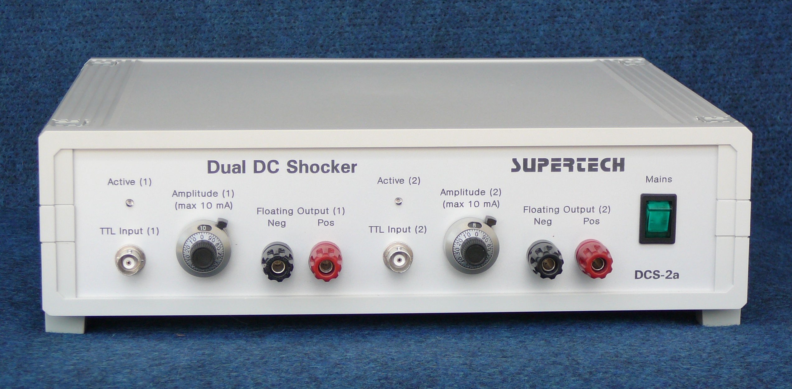
Development Example (3), Dual DC Shocker DCS-2a
 Click on the picture to get it in full size
Dual DC Shocker DCS-2a is the dual-channel version of the default DC Shocker. It is a self-powered version, it contains built-in mains power supply. Dual DC Shocker DCS-2a can be used as stand-alone equipment, connected to and controlled by any other data acquisition system, not only from the Modular Behavioral System.
The complete User Manual of the Dual DC Shocker DCS-2x is available for download.
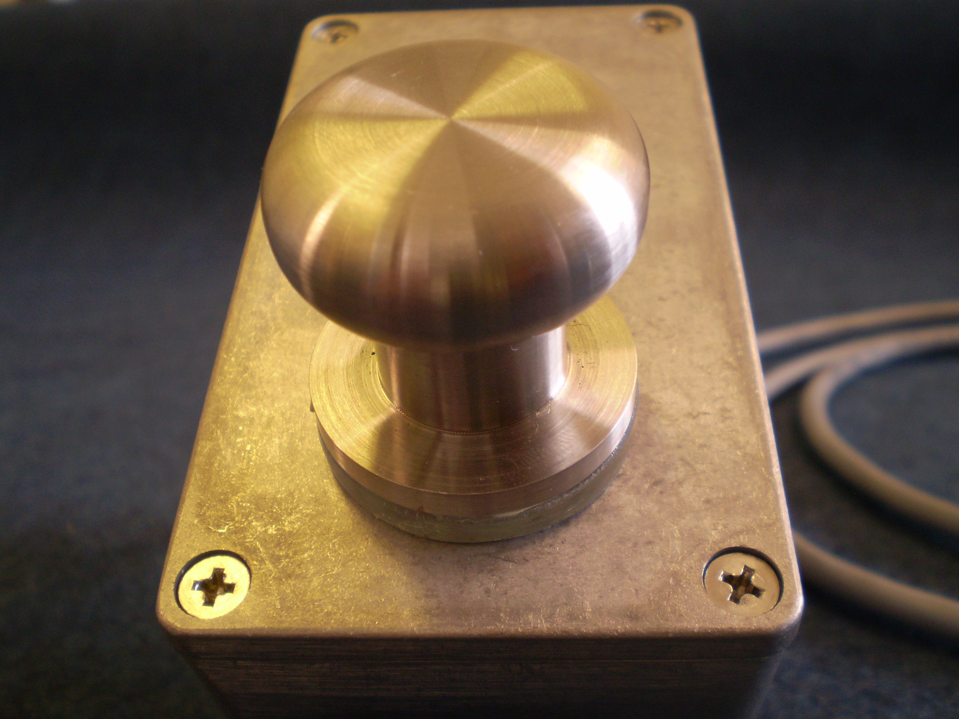
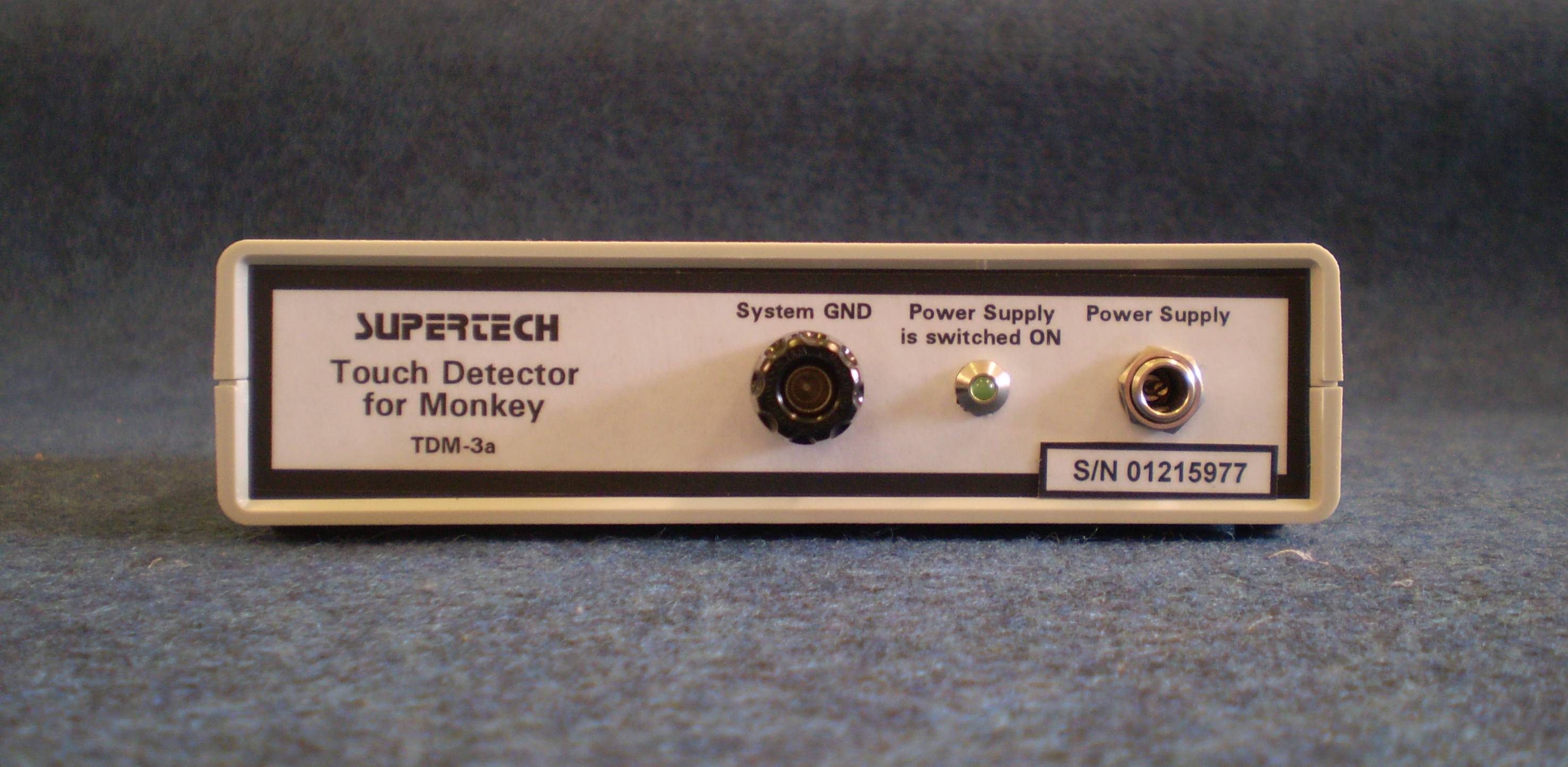
Development Example (4), Touch Detector for Monkey MBTD-1

 Click on the picture to get it in full size
Monkeys are very strong. The touch button is built in an extremely robust aluminum box, so it can not be ruined by the animal. It can be assembled anywhere close to the hand of the monkey. The touch button is a stainless steel ellipsoidal part. Its size is comfortable for the monkey to grab. The touch button is assembled on the aluminum box hard, without any moving part.
Touch Detector for Monkey is universally adaptable to any behavioral lab. It can be used either with the Modular Behavioral System or in a 3rd-party behavioral conditioning system. By its standard TTL output it can be connected to any data acquisition system.
The aluminum enclosure of the touch button is hermetically sealed. It can be washed, sanitized and/or sterilized.
The touch button indicates the touch actions on capacitive way. For the reliable operation the body of the animal should have been grounded. Grounding of the monkey can be carried out on two ways. If the chair he/she sits is made of metal, it is enough to connect the chair to the GND potential. If the chair of the monkey is made of an insulator material, a grounded stainless steel plate should be put on the chair under the bottom of the animal.
The capacitive sensor circuit is located in the robust aluminum box. The signal conditioning circuits are realized as a usual-looking electronic equipment. The signal conditioner box and its plug-in DC power supply should be put far away from the monkey. The built-in cable of the touch button box is long enough to allow it.
Output of the signal conditioner box: TTL compatible, 10 unit-loads capability
Active level (when touched): TTL High
Prices
You can find the general warranty and shipping conditions in the beginning of the Services page.
Power Supply Module MBPS-3: 480 EUR
12-bit USB System Controller MBSC-1: 684 EUR
4-channel TTL Input Control Module MBTTLI-1: 252 EUR
4-channel TTL Output Control Module MBTTLO-1: 288 EUR
Sound Generator End-stage MBSG-1, plus a wideband loudspeaker: 228 EUR
DC Shocker Controller PDC-2, as a part of the Modular Behavioral System. This version has no its own power supply, it is powered by the Power Supply Module MBPS-3: 576 EUR
DC Shocker Controller PDC-2a, as a stand-alone equipment. This version contains a built-in mains power supply: 744 EUR
DC Shocker DCS-4 (1-channel, floating, isolated), as a part of the Modular Behavioral System. This version has no its own power supply, it is powered by the Power Supply Module MBPS-3: 816 EUR
DC Shocker DCS-4a (1-channel, floating, isolated), as a stand-alone equipment. This version contains a built-in mains power supply: 984 EUR
Dual DC Shocker DCS-2a (2-channel, floating, isolated), as a stand-alone equipment. This version contains a built-in mains power supply: 1404 EUR
Touch Detector for Monkey MBTD-1 (Complete set: Touch Button Box, Signal Conditioner Box and Plug-in DC Power Supply together): 1596 EUR
Windows-based behavioral control program "Automated Stimulus Control v1.5" and its customized versions are available from its developer and intellectual property owner SnowGiraffe Ltd. directly. The annual license fee of version 1.5 is: 480 EUR
![]()
![]()
![]()
![]()
![]()
![]()
![]()
![]()
Copyright @ Supertech Instruments - since 1991